Home/
Registry/
Hyundai/
Genesis Coupe/
2010-2016/
“Coupe”/
Photo
supermotors.net/registry/media/1072201
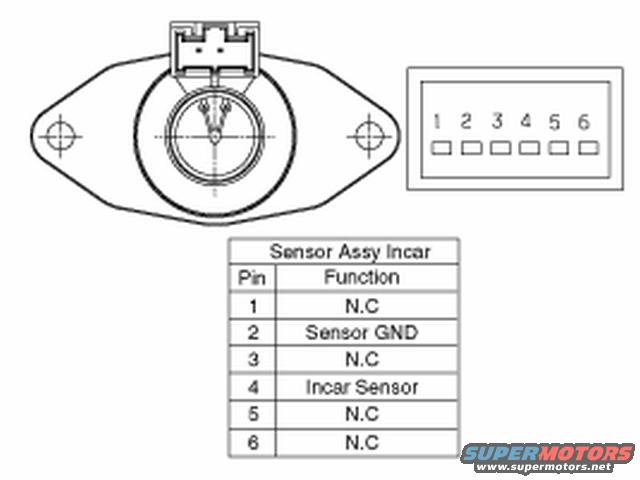
Hyundai Genesis Coupe In-Car Temperature Sensor Connector Pinout Diagram
Reference · 2010-2016 Genesis CoupeAll 23 schematics
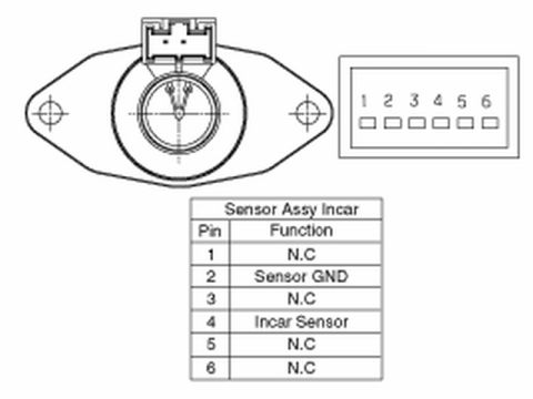








Schematic of an in-car temperature sensor assembly showing the connector and a 6-pin function table identifying sensor ground and signal pins.
Part of 2010-2016 Hyundai Genesis Coupe Schematics
This document is a schematic/pinout diagram for an in-car temperature sensor assembly (labeled "Sensor Assy Incar"), uploaded as part of a 2010 Hyundai Genesis Coupe reference album. The image shows a line drawing of the oval-shaped sensor assembly viewed from the face, with two mounting holes on the flanges, a central round aspirator/sensor opening, and a 6-pin connector on top. A separate connector face view shows the pin numbering from 1 to 6. Below the drawings is a table listing the function of each connector pin: pins 1, 3, 5, and 6 are N.C (not connected), pin 2 is Sensor GND (sensor ground), and pin 4 is the Incar Sensor signal. From this document a reader can identify which two terminals of the six-pin connector are actually used by the in-car temperature sensor circuit, pin 2 for ground and pin 4 for the sensor signal, which is useful for testing the sensor, checking wiring continuity, or diagnosing climate control (HVAC) faults related to cabin temperature sensing. The document itself contains no year, model, part number, wire color, or torque information.
Is this accurate? Sign in to help verify it.
Frequently asked questions
- Which pin is the in-car sensor signal on the 6-pin connector?
- Pin 4 is labeled 'Incar Sensor' in the pin function table.
- Which pin is ground on the in-car temperature sensor connector?
- Pin 2 is labeled 'Sensor GND'.
- Which pins on the in-car sensor connector are not connected?
- Pins 1, 3, 5, and 6 are all listed as N.C (not connected).
- How many pins does the in-car sensor assembly connector have?
- The connector has 6 pins, numbered 1 through 6, though only pins 2 and 4 are used.

No comments yet.