Home/
Registry/
Hyundai/
Genesis Coupe/
2010-2016/
“Coupe”/
Photo
supermotors.net/registry/media/763572
Hyundai Genesis ESC System Diagram - HECU, Wheel Speed & Yaw-Rate Sensors

Reference · 2010-2016 Genesis CoupeAll 23 schematics
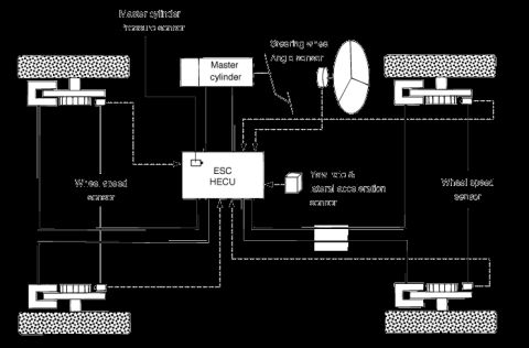








System schematic of an ESC HECU connected to wheel-speed sensors, master cylinder, steering angle, and yaw-rate sensors.
Part of 2010-2016 Hyundai Genesis Coupe Schematics
This document is a system layout schematic for an Electronic Stability Control (ESC) system, uploaded to the gallery of a 2010 Hyundai Genesis. It shows a top-down view of a vehicle's four wheels/brake assemblies connected to a central ESC HECU (Hydraulic and Electronic Control Unit). Solid heavy lines depict hydraulic brake lines running from the master cylinder through the ESC HECU to each of the four wheel brake calipers. Dotted lines depict electrical sensor signal paths. The inputs to the ESC HECU shown are: a master cylinder pressure sensor, a steering wheel angle sensor (drawn at the steering wheel), a combined yaw-rate and lateral acceleration sensor, and four wheel speed sensors (one at each wheel, labeled on both the left and right sides of the diagram). A reader can learn the overall architecture of the ESC system, which sensors feed the control unit and how the hydraulic circuit is routed from the master cylinder through the HECU to all four brakes. The diagram contains no part numbers, wire colors, connector pinouts, fuse data, or year/model applicability statements; it is purely a component-location/signal-flow overview.
Is this accurate? Sign in to help verify it.
Frequently asked questions
- What sensors provide input to the ESC HECU in this diagram?
- The diagram shows the ESC HECU receiving inputs from the master cylinder pressure sensor, the steering wheel angle sensor, the yaw-rate & lateral acceleration sensor, and four wheel speed sensors (one at each wheel).
- How many wheel speed sensors are shown?
- Four: one at each wheel, with 'Wheel speed sensor' labeled on both the left and right sides of the diagram.
- Where is the steering wheel angle sensor located in the diagram?
- It is shown at the steering wheel, with a dotted signal line running to the ESC HECU.
- What does the ESC HECU connect to hydraulically?
- Solid lines show the master cylinder connecting to the ESC HECU, which then routes hydraulic lines to all four wheel brake assemblies.
- Does this diagram list fuse ratings or wire colors?
- No. It is a component/signal-flow schematic only; it contains no fuse positions, amp ratings, wire colors, or part numbers.

No comments yet.