Home/
Registry/
Hyundai/
Genesis Coupe/
2010-2016/
“Coupe”/
Photo
supermotors.net/registry/media/1107571
Hyundai Genesis Coupe M48-L Multifunction Switch Connector Pinout Diagram

Reference · 2010-2016 Genesis CoupeAll 23 schematics
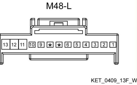








Connector pinout drawing of connector M48-L showing the terminal cavity layout with numbered positions.
Part of 2010-2016 Hyundai Genesis Coupe Schematics
This document is a connector pinout diagram identified as "M48-L". It shows the face (cavity) view of a 13-position electrical connector housing. Pin cavities are numbered from left to right as 13, 12, 11, 10, 9, then two positions marked with asterisks (indicating unused/blocked cavities, i.e., positions 8 and 7 are not populated), followed by 6, 5, 4, 3, 2, 1. Pins 13, 12, and 11 are drawn as larger cavities than the remaining smaller cavities, suggesting a mix of terminal sizes. The connector housing outline includes a locking tab at the top. The bottom-right corner carries the connector drawing code "KET_0409_13F_W", which appears to identify the connector as a KET-type 13-way female connector. According to the uploader, this diagram represents the multifunction switch (MFS) connector for a 2013 Hyundai Genesis Coupe, though the document itself contains no vehicle, year, or model information. A reader can use this diagram to identify pin cavity locations and numbering when probing or repairing wiring at connector M48-L.
Is this accurate? Sign in to help verify it.
Frequently asked questions
- How many pin positions does connector M48-L have?
- The diagram shows 13 numbered positions (1 through 13), with two positions marked by asterisks (between 9 and 6) indicating unpopulated/blocked cavities, plus larger cavities for pins 11, 12, and 13.
- What is the pin numbering order on connector M48-L?
- Viewed as drawn, pins run left to right: 13, 12, 11, 10, 9, two asterisk (unused) positions, then 6, 5, 4, 3, 2, 1.
- What connector code is shown on the M48-L diagram?
- The drawing carries the code KET_0409_13F_W in the lower right corner.
- Are all cavities the same size on connector M48-L?
- No. Positions 13, 12, and 11 are drawn as larger cavities, while the remaining positions are smaller cavities.

No comments yet.