Home/
Registry/
Hyundai/
Genesis Coupe/
2010-2016/
“Coupe”/
Photo
supermotors.net/registry/media/1099250
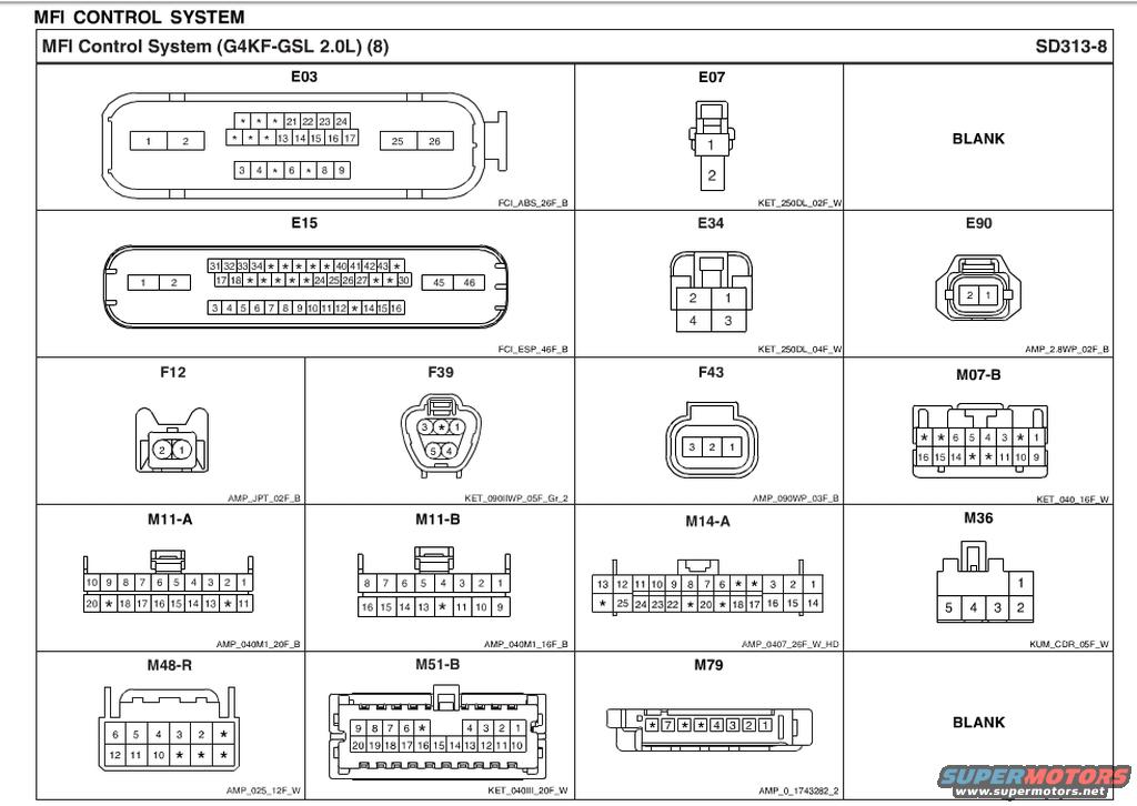
Hyundai Genesis Coupe 2.0L G4KF MFI Control Connector Pinouts SD313-8
Reference · 2010-2016 Genesis CoupeAll 23 schematics
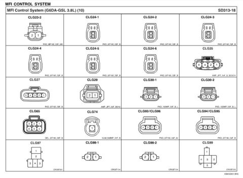
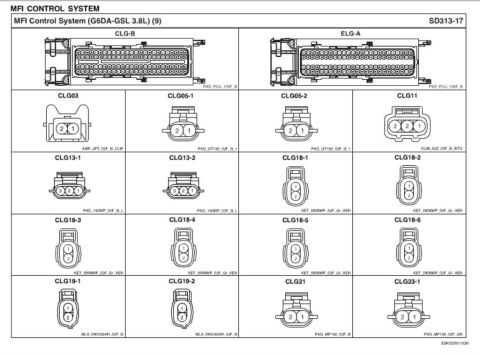
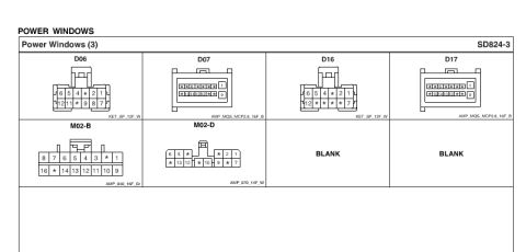
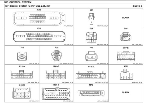
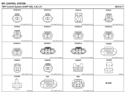
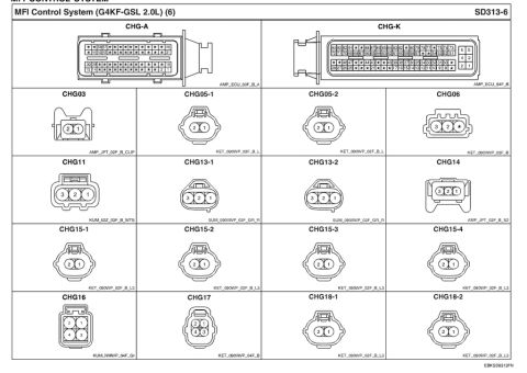
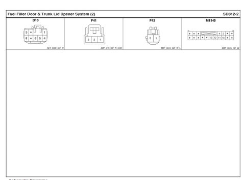








Connector pinout reference chart for an MFI control system listing connector faces with pin numbering and part numbers.
Part of 2010-2016 Hyundai Genesis Coupe Schematics
This document is page 8 (sheet SD313-8) of the MFI (Multiport Fuel Injection) Control System wiring reference for the G4KF-GSL 2.0L engine, consistent with a Hyundai Genesis Coupe 2.0T service manual set. It is a connector identification chart showing pinout face views for the harness connectors used in the MFI control system circuits. Connectors depicted include E03 (26-pin, FCI_ABS_26F_B), E07 (2-pin), E15 (46-pin, FCI_ESP_46F_B), E34 (4-pin), E90 (2-pin), F12 (2-pin), F39 (6-cavity round), F43 (3-pin), M07-B (16-pin), M11-A (20-pin), M11-B (16-pin), M14-A (26-pin), M36 (5-pin), M48-R (12-pin), M51-B (20-pin), and M79 (8-pin). Each cell shows the connector cavity numbering as viewed on the connector face (asterisks mark unused/unlabeled cavities) plus a connector housing code (e.g., AMP_040M1_20F_B, KET_250DL_02F_W) identifying the connector series, cavity count, gender, and color. A reader can use this page to locate specific pin numbers on each connector when performing electrical diagnostics or repairs on the 2.0L MFI control system, cross-referencing the connector IDs used in the associated MFI wiring diagrams.
Is this accurate? Sign in to help verify it.
Frequently asked questions
- What engine does this MFI connector diagram cover?
- It covers the MFI Control System for the G4KF-GSL 2.0L engine, per the page heading 'MFI Control System (G4KF-GSL 2.0L) (8)', sheet SD313-8.
- How many pins does connector E15 have and what is its housing code?
- E15 is a 46-pin connector with housing code FCI_ESP_46F_B; numbered cavities shown include 1-18, 24-27, 30-34, 40-43, 45 and 46.
- What is the pinout of connector M11-A?
- M11-A is a 20-cavity connector (code AMP_040M1_20F_B) with top row pins 10 9 8 7 6 5 4 3 2 1 and bottom row 20 * 18 17 16 15 14 13 * 11 (asterisks are unused cavities).
- What connector type is E07?
- E07 is a 2-pin connector (pins 1 and 2) with housing code KET_250DL_02F_W.
- What is connector F39?
- F39 is a round 6-cavity connector with populated pins 1, 3, 4 and 6, housing code KET_090IIWP_05F_Gr_2.

No comments yet.