Home/
Registry/
Hyundai/
Genesis Coupe/
2010-2016/
“Coupe”/
Photo
supermotors.net/registry/media/1099248
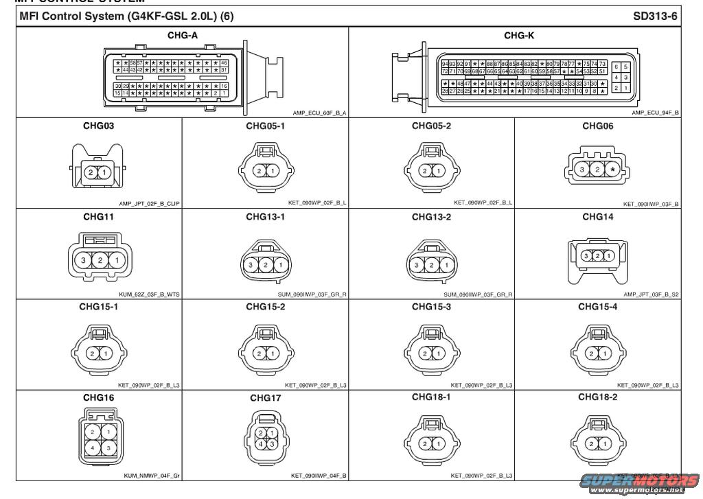
Hyundai Genesis Coupe 2.0L G4KF MFI Connector Views - ECU Pinouts SD313-6
Reference · 2010-2016 Genesis CoupeAll 23 schematics
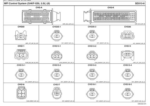








Schematic showing MFI control system connector pinout layouts (CHG-A, CHG-K, and numbered sub-connectors) for a Hyundai G4KF 2.0L engine.
Part of 2010-2016 Hyundai Genesis Coupe Schematics
This document is page SD313-6 from a Hyundai wiring/service diagram set, titled "MFI Control System (G4KF-GSL 2.0L) (6)." It is a connector view (schematic legend) sheet showing physical face views and pin numbering for the connectors used in the Multiport Fuel Injection (MFI) control system on the G4KF 2.0L gasoline engine. At the top are the two main ECU connectors: CHG-A, a 60-pin connector (AMP_ECU_60F_B_A), and CHG-K, a 94-pin connector (AMP_ECU_94F_B), each with pin cavity numbering shown (unused/unlabeled cavities marked with stars). Below are sixteen smaller in-harness connectors labeled CHG03 through CHG18-2, each drawn with its terminal numbers and its housing part code: 2-pin connectors (CHG03, CHG05-1/2, CHG15-1 through 15-4, CHG18-1/2), 3-pin connectors (CHG06, CHG11, CHG13-1/2, CHG14), and 4-pin connectors (CHG16, CHG17). Housing codes include KET_090WP_02F_B_L3, SUM_090IIWP_03F_GR_R, KUM_62Z_03F_B_WTS, AMP_JPT_03F_B_S2 and others. A reader can use this page to identify connector shapes, pin orientation, and housing types when tracing or repairing MFI system wiring. Footer reference: EBKSD9313FN.
Is this accurate? Sign in to help verify it.
Frequently asked questions
- What engine does this MFI connector diagram cover?
- The page is titled "MFI Control System (G4KF-GSL 2.0L) (6)", so it covers the G4KF-GSL 2.0L gasoline engine.
- How many pins do the ECU connectors CHG-A and CHG-K have?
- CHG-A is a 60-pin ECU connector (AMP_ECU_60F_B_A) and CHG-K is a 94-pin ECU connector (AMP_ECU_94F_B).
- What connector housing is used for CHG15-1 through CHG15-4?
- All four CHG15 connectors are 2-pin connectors with housing code KET_090WP_02F_B_L3.
- Which connectors on this page are 4-pin?
- CHG16 (KUM_NMWP_04F_Gr) and CHG17 (KET_090IIWP_04F_B) are 4-pin connectors, each showing pins 1-4.
- What is the diagram reference number for this page?
- The page is labeled SD313-6, with footer code EBKSD9313FN.

No comments yet.