Home/
Registry/
Ford/
Bronco/
1978-1979/
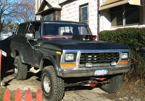
“Black Betty”/
Photo
supermotors.net/registry/media/1105100
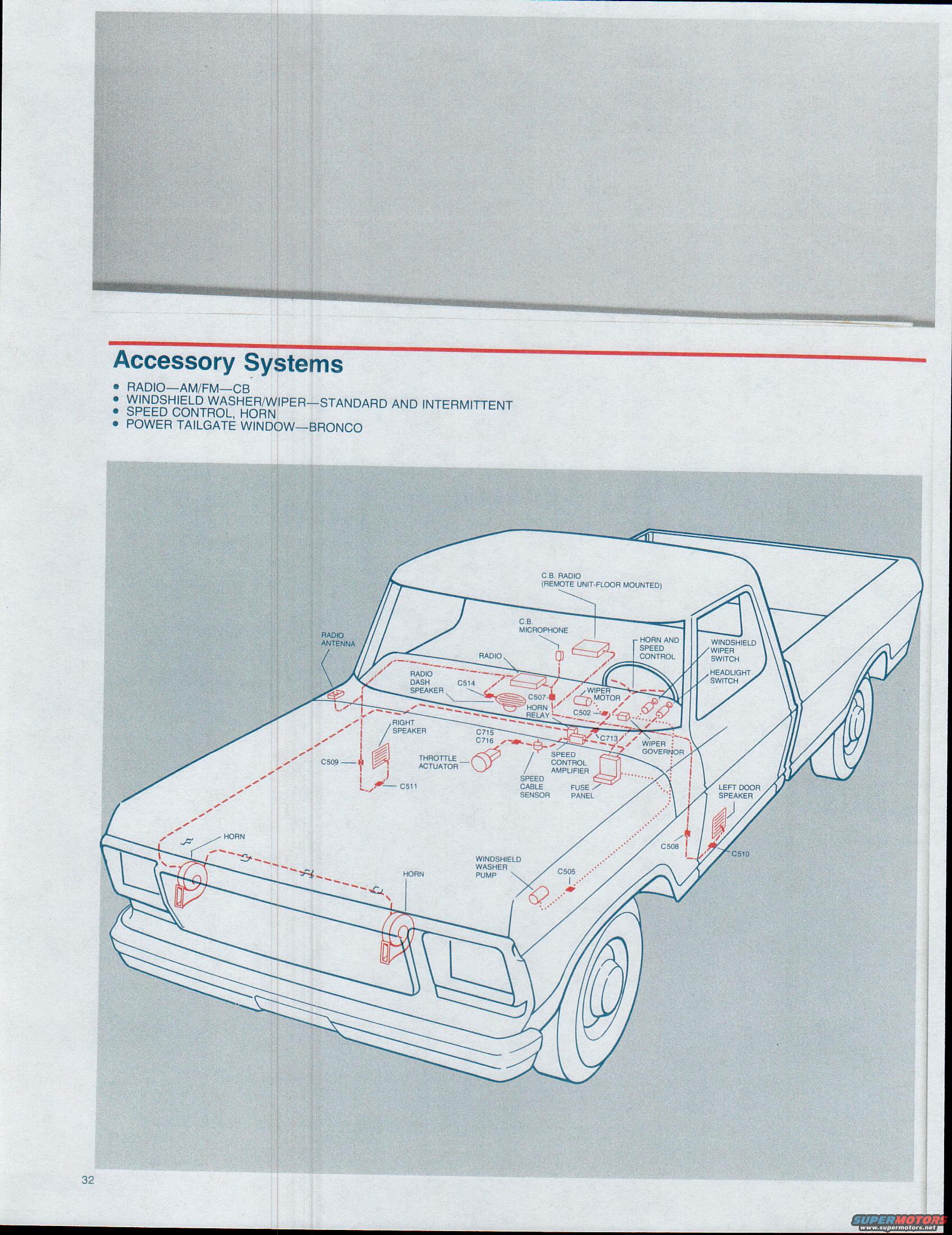
1979 Ford Bronco & F100-F350 Accessory Systems Component Location Diagram
Reference · 1978-1979 BroncoAll 44 schematics
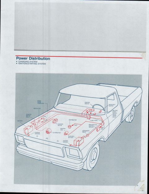



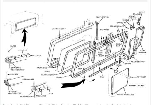
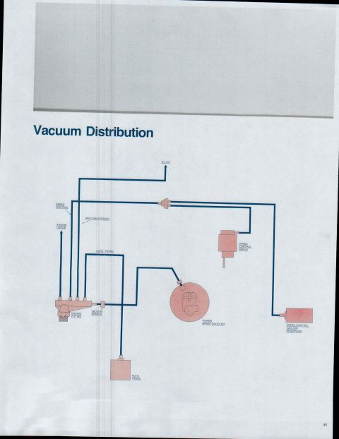
Pictorial component location diagram over a Ford pickup outline showing accessory system parts: radio, CB, wiper, speed control actuator, horn and power tailgate window wiring.
Part of 1978-1979 Ford Bronco Schematics
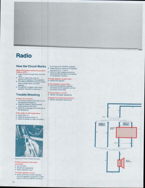
This document is page 32 of a Ford wiring/electrical reference covering the 1979 Bronco and F100 through F350 trucks. The page introduces the "Accessory Systems" section, which covers the AM/FM/CB radio, the standard and intermittent windshield washer/wiper systems, the speed control and horn, and the Bronco power tailgate window. The bulk of the page is an isometric component-location illustration of a pickup truck showing the physical locations and wiring harness routing (drawn in red) for accessory system components. Labeled components include the C.B. radio (remote unit, floor mounted), C.B. microphone, radio, radio antenna, radio dash speaker, right speaker, left door speaker, horn relay, horns (two shown at front of vehicle), wiper motor, wiper governor, windshield wiper switch, headlight switch, windshield washer pump, horn and speed control, throttle actuator, speed control amplifier, speed cable sensor, and the fuse panel. Numbered wiring connectors are called out at their locations: C502, C505, C507, C508, C509, C510, C511, C514, C713, C715, and C716. A reader can use this page to locate accessory-system components and harness connectors on the vehicle before consulting the following schematic pages.
Is this accurate? Sign in to help verify it.
Frequently asked questions
- What systems are covered in the Accessory Systems section?
- Radio (AM/FM and CB), windshield washer/wiper (standard and intermittent), speed control, horn, and the power tailgate window on the Bronco.
- Which connector numbers are shown on the accessory systems location diagram?
- C502, C505, C507, C508, C509, C510, C511, C514, C713, C715, and C716.
- Where is the CB radio mounted according to this diagram?
- The C.B. radio is a remote unit that is floor mounted, with a separate C.B. microphone near the dash.
- What speed control components are shown in the diagram?
- The horn and speed control (steering wheel area), throttle actuator, speed control amplifier, and speed cable sensor, plus connectors C713, C715 and C716.
- Is the power tailgate window covered for all trucks?
- No: the page lists the power tailgate window as a Bronco-only item.
No comments yet.