Home/
Registry/
Ford/
Bronco/
1978-1979/
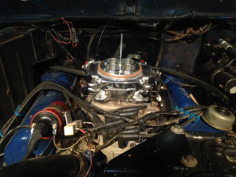
“Black Betty”/
Photo
supermotors.net/registry/media/1105102
1979 Ford Bronco/F100-F350 Radio Circuit Troubleshooting & Wiring Diagram
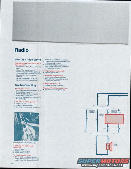
Service manual radio page describing how the circuit works (power through fuse 10 in RUN/ACCY) plus trouble-shooting steps for no sound and a 2-4 ohm speaker resistance check.
This is page 34 of a Ford factory-style electrical troubleshooting guide (filed as covering the 1979 Bronco and F100 through F350 trucks), covering the Radio circuit. The 'How the Circuit Works' section explains that with the ignition switch in RUN or ACCY, power travels through fuse 10 to the radio; AM and AM/FM monaural radios use a single dash-mounted speaker, while the AM/FM multiplex radio has a speaker in each door. The 'Trouble-Shooting' section gives step-by-step diagnostics: if there is no sound, verify the tuner is on a broadcasting frequency, check the antenna lead, and check speaker connectors; if still inoperative, check fuse 10, power to fuse 10, and power at the radio connector (a photo shows checking for power at the radio connector with a test light). Speaker circuit checks include continuity at speaker connections, 2-4 ohm speaker resistance, and listening for a popping sound with a self-powered test light. Remedies cover single-speaker failure (replace speaker), dual-speaker failure (check wiring between speaker and radio connectors), and speaker replacement if wiring checks out. A partial wiring diagram shows connector C514, black (bk) and brown (br) wires, 'Without CB Radio' and 'With CB Radio' branches, the CB radio relay, and the radio speaker.
Is this accurate? Sign in to help verify it.
Frequently asked questions
- Which fuse powers the radio in the 1979 Ford Bronco/F-Series?
- Per this document, power travels through fuse 10 to the radio when the ignition switch is turned to RUN or ACCY. If the radio is inoperative, check fuse 10, power to fuse 10, and power at the radio connector.
- Where are the radio speakers located?
- AM and AM/FM monaural radios have a single dash-mounted speaker; the AM/FM multiplex radio has a speaker mounted in each door.
- What resistance should the speaker circuit show?
- The document says to check the speaker connections for a speaker resistance of 2 - 4 ohms, and to listen for a slight popping sound as a self-powered test light is connected to the speaker circuit(s).
- What should I check first if the radio produces no sound?
- Turn the tuner to make sure the radio is on a broadcasting frequency, check for a loose or disconnected antenna lead at the radio, and check for unplugged connector(s) at the speaker(s).
- What connector and wire colors are shown in the radio speaker wiring diagram?
- The diagram shows connector C514, black (bk) and brown (br) wires, branches labeled 'Without CB Radio' and 'With CB Radio', a CB Radio Relay, and the Radio Speaker.
Comments
More from this build






No comments yet.