Home/
Registry/
Ford/
Bronco/
1992-1996/
1996 Ford Bronco/
Photo
supermotors.net/registry/media/1110348
1996 Ford Bronco/F-150 ABS Code 25 Pinpoint Test E - Front Right Solenoid Valve
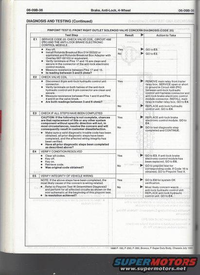
4WABS Pinpoint Test E (Code 25) front right outlet solenoid valve diagnosis steps; checks valve coil resistance on circuit 498 PK, expecting 3-6 ohms between pins 17 and 15.
This page is from the 1996 Ford Body/Chassis service manual (section 06-09B-36, Brake, Anti-Lock, 4-Wheel) covering the 1996 F-150, F-250, F-350, Bronco, and F-Super Duty. It presents Pinpoint Test E: Front Right Outlet Solenoid Valve Concern Diagnosis (Code 25) for the 4-wheel anti-lock brake system. The procedure is laid out as a step-by-step diagnostic table (steps E1–E5) with test steps, yes/no results, and corresponding actions. Step E1 checks the valve coil, Circuit 498 (PK), and the ABS electronic control module using a Rotunda Breakout Box 014-00322 with Overlay 007-00103, measuring resistance between Pins 17 and 15 (spec: 3–6 ohms). E2 checks the valve coil at the 8-pin anti-lock hydraulic control unit connector (Pins 1–8 and 4–8, 3–6 ohms), leading either to servicing Circuit 498 (PK) or replacing the hydraulic control unit. E3 verifies all prior diagnostic steps were completed before replacing the ABS electronic control module. E4 verifies the condition is resolved by clearing and re-retrieving codes, with a branch to Pinpoint Test X if Code 16 appears. E5 verifies vehicle wiring integrity via Pinpoint Test W (intermittent diagnosis). A reader learns exactly how to diagnose ABS Code 25 and which components to service or replace.
Is this accurate? Sign in to help verify it.
Frequently asked questions
- What does ABS Code 25 mean on a 1996 Ford Bronco or F-Series truck?
- Code 25 indicates a front right outlet solenoid valve concern, diagnosed via Pinpoint Test E, which checks the valve coil, Circuit 498 (PK), and the anti-lock brake electronic control module.
- What resistance should the front right outlet solenoid valve coil read?
- Resistance measured between Pins 17 and 15 at the ABS module connector, and between Pins 1 and 8 and Pins 4 and 8 on the valve block, should be between 3 and 6 ohms.
- What special tools are needed for this ABS pinpoint test?
- A Rotunda Breakout Box 014-00322 or equivalent and Rotunda Breakout Box Adapter with Overlay 007-00103 or equivalent.
- What if the valve coil readings in step E2 are out of range?
- If both readings are not between 3 and 6 ohms, REPLACE the anti-lock hydraulic control unit and GO to E4 to verify the condition is resolved.
- What should I do if Code 16 appears during verification (E4)?
- If Code 16 is obtained when retrieving codes in step E4, GO to Pinpoint Test X.
Comments
More from this build


No comments yet.