Home/
Registry/
Ford/
Bronco/
1992-1996/
1996 Ford Bronco/
Photo
supermotors.net/registry/media/1110350
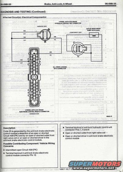
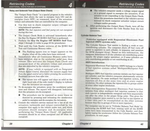
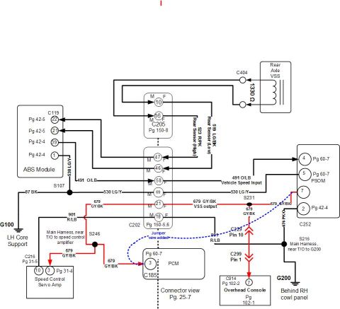
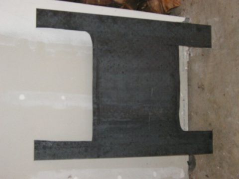
This diagram details the wiring for the anti-lock brake system's electronic control module and hydraulic control unit.
Brake, Anti-Lock, 4-Wheel 06-093-35 AGNOSIS AND TESTING (Continued) Affected Circuit(s)/ Electrical Component(s) LWHEEL ANTH.OCK BRAKE HYDRAULK: ML LIIIT OONNEGTOR HARNESS SIDE . OUTLET Hem FRONT bum VALVE (em) COMPONENT SIDE 6 f O O o o 498 a 4 PK V ALL VIEWS LOOKING INTO CONNECTOR LA '5 L '5 '5' '. F t LWHEE. ANTI-LOCK BRAKE HECTRONIC CONTROL MODULE CONNECTOR HARNESS SIDE m-D Description 0 Terminal backout in anti-lock hydraulic control unit Code 25 is generated by the anti-lock brake electronic connector P'"s 1' 4 and 8 control modules detection of an open or shorted 0 Open or shorted outlet front right valve coil - Qircwt 498 (PK) and by an open or shorted outlet front 0 Open or shorted driver in anti-lock brake electronic nght valve corl or an open or shorted driver In the control module anti-lock brake electronic control module. Possible Contributing Component/ Vehicle Wiring Concerns 3 Intermittent open Circuit 498 (PK) 0 Terminal backout in anti-lock brake electronic control module connector Pin 15 I 1996 F-150, F-250. F-350, Bronco, F-Super Duty Body. Chassis July 1995 /
Comments
More from this build


No comments yet.