Home/
Registry/
Ford/
Bronco/
1992-1996/
“Buckin Bronco”/
Photo
supermotors.net/registry/media/1110669
1994 Ford Bronco/F-Series C202 In-Line Connector Pinout - Wire Circuit Chart
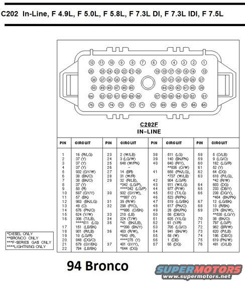
Wiring diagram of Ford C202 in-line connector with numbered pin layout and pin-to-circuit color-code table for F-series 4.9L-7.5L engines.
Part of 1992-1996 Ford Bronco Wiring Diagrams
This document is a pinout reference for the Ford C202 in-line electrical connector (labeled C202F IN-LINE), applicable to the 4.9L, 5.0L, 5.8L, 7.3L DI, 7.3L IDI, and 7.5L engines, with the caption '94 Bronco.' It shows a face-view diagram of the 76-pin in-line connector with pin numbering arranged in six rows, followed by a complete pin-to-circuit table. Each of the 76 pins is listed with its circuit number and wire color code (e.g., pin 1 = circuit 16 R/LG, pin 11 = circuit 57 BK, pin 39 = circuit 140 BK/PK). Several pins carry alternate circuits depending on application, indicated with asterisk footnotes: *diesel only, **Bronco only, ***F-Series gas only, ****Lightning only. For example, pin 29 is circuit 32 (R/LB) with 342 (LG/P) on diesel and Lightning, pin 30 adds 887 (Y) on Bronco, and pin 16 has 511 (LG) on Lightning only. This chart lets a reader identify which wire and circuit connects to any given cavity of the C202 bulkhead/in-line connector when diagnosing wiring problems on 1994 Ford Bronco and F-Series trucks across gas and diesel engine variants.
Is this accurate? Sign in to help verify it.
Frequently asked questions
- What connector does this diagram cover?
- The C202 (C202F) in-line connector, a 76-pin connector used on F 4.9L, F 5.0L, F 5.8L, F 7.3L DI, F 7.3L IDI, and F 7.5L applications, captioned '94 Bronco.'
- What circuit and wire color is on pin 1 of C202?
- Pin 1 is circuit 16 with wire color R/LG (red/light green).
- What do the asterisk footnotes in the pin table mean?
- * = diesel only, ** = Bronco only, *** = F-Series gas only, **** = Lightning only. Pins with asterisked circuits use different circuits depending on the application.
- Which pin carries circuit 57 (BK), the ground circuit color black?
- Pin 11 is circuit 57 (BK).
- Are any pins unused on the C202 connector?
- Yes, pin 26 is shown with a dash, indicating no circuit is listed for it.
Comments
More from this build














No comments yet.