Home/
Registry/
Ford/
Bronco/
1992-1996/
“Buckin Bronco”/
Photo
supermotors.net/registry/media/1116040
Ford 5.0L PCM Connector C185 Pinout Diagram - 104-Pin Wiring & Wire Colors
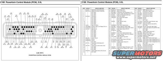
Powertrain Control Module C185 connector pinout chart listing pin numbers, circuits and functions for the 5.0L engine.
This document is a two-panel reference for connector C185, the 104-pin Powertrain Control Module (PCM) connector on a Ford 5.0L engine. The left panel shows the physical connector face (labeled C185 GRAY, POWERTRAIN CONTROL MODULE (PCM)) with all 104 pin cavities drawn and callout lines identifying the circuit number and wire color for each populated pin (e.g., 315 P/O, 658 PK/LG, 570 BK/W). The right panel is a complete pinout table listing all 104 pins with their circuit number, wire color code, and circuit function. Key circuits include transmission shift solenoids #1 and #2, MIL, data link lines (FEPS, DL+ and DL−), sensor inputs (ECT, IAT, TFT, CKP, TP, MAF, VSS, HEGO sensors #11/#12/#21 and their heater monitors), outputs such as SPOUT, EPC, IAC, EGR control, EVAP purge, fuel pump enable/monitor, TCC and coast clutch solenoids (E4OD only), OSS (4R70W only), and fuel injector outputs #1-#8. Grounds, keep-alive power, and Hot-in-Start-or-Run power feeds are also identified. Many pins are marked NOT USED. This allows a reader to identify any PCM pin's wire color and function for diagnostics or wiring repair on a 5.0L application.
Is this accurate? Sign in to help verify it.
Frequently asked questions
- What is connector C185 on a Ford 5.0L?
- C185 is the gray 104-pin Powertrain Control Module (PCM) connector for the 5.0L engine; this document shows its pin layout and full pinout table.
- Which PCM pins control the fuel injectors on the 5.0L?
- Injector outputs are pin 75 (555 T, #1), 101 (556 W, #2), 74 (557 BR/Y, #3), 100 (558 BR/LB, #4), 73 (559 T/BK, #5), 99 (560 LG/O, #6), 72 (561 T/R, #7), and 98 (562 LB, #8).
- What pin is the Throttle Position (TP) Sensor on C185?
- Pin 89, circuit 355 (GY/W), is the Throttle Position (TP) Sensor input.
- Which C185 pins are grounds?
- Pins 24, 51, 76, 77, and 103 are Ground (570 BK/W), pin 25 is Ground (875 BK/LB), and pin 23 is Ignition Ground (259 O/R).
- What wire color is the Vehicle Speed Sensor (VSS) input to the PCM?
- The VSS input is pin 58, circuit 679 (GY/BK); the VSS ground is pin 33, circuit 676 (PK/O).
Comments
More from this build














No comments yet.