Home/
Registry/
Ford/
Bronco/
1992-1996/
“Buckin Bronco”/
Photo
supermotors.net/registry/media/1116047
Ford 4R70W Transmission Wiring Diagram - PCM Power Relay & Speed Sensor (29-3)
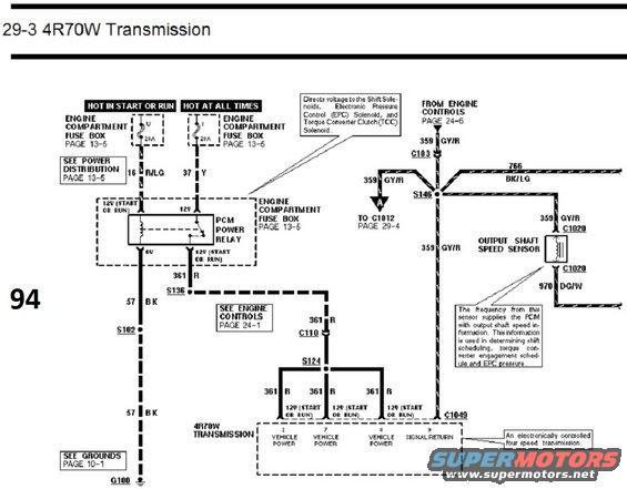
Wiring schematic for the Ford 4R70W automatic transmission showing PCM power relay feed, EPC/TCC solenoid circuits and the output shaft speed sensor (circuit 970 DG/W).
This is page 29-3 of a Ford factory wiring diagram (EVTM) covering the 4R70W four-speed electronically controlled automatic transmission. It shows the power feed portion of the transmission circuit: two 20A fuses in the engine compartment fuse box (one hot in start or run via circuit 16 R/LG, one hot at all times via circuit 37 Y) feed the PCM Power Relay, which is also housed in the engine compartment fuse box (see page 13-5). The relay output on circuit 361 R passes through splices S136 and S124 and connector C110 to supply Vehicle Power to pins 2, 7, and 8 of the 4R70W transmission connector C1049. Relay ground is via circuit 57 BK through splice S102 to ground G100 (see grounds page 10-1). The diagram also shows the signal return circuit 359 GY/R from Engine Controls (page 24-6) through C103 and splice S146, feeding the Output Shaft Speed Sensor (via connectors C1020, with signal wire 970 DG/W and shield 766 BK/LG) and pin 9 (Signal Return) of C1049. Notes explain the relay directs voltage to the shift solenoids, EPC solenoid and TCC solenoid, and that the output shaft speed sensor frequency is used by the PCM for shift scheduling, torque converter engagement and EPC pressure.
Is this accurate? Sign in to help verify it.
Frequently asked questions
- What fuses power the 4R70W transmission circuit?
- Two 20A fuses in the engine compartment fuse box (page 13-5): one hot in start or run feeding circuit 16 R/LG and one hot at all times feeding circuit 37 Y, both supplying the PCM Power Relay.
- What does the PCM Power Relay do in this circuit?
- It directs voltage to the Shift Solenoids, Electronic Pressure Control (EPC) Solenoid, and Torque Converter Clutch (TCC) Solenoid via circuit 361 R (12V in start or run).
- Which pins on the 4R70W transmission connector C1049 receive vehicle power?
- Pins 2, 7, and 8 receive Vehicle Power on circuit 361 R (12V in start or run); pin 9 is Signal Return on circuit 359 GY/R.
- What wire colors are used for the output shaft speed sensor?
- The sensor connects through C1020 with circuit 359 GY/R and circuit 970 DG/W, with a shield drain circuit 766 BK/LG.
- What is the output shaft speed sensor signal used for?
- Its frequency supplies the PCM with output shaft speed information, used in determining shift scheduling, torque converter engagement schedule and EPC pressure.
Comments
More from this build














No comments yet.