Home/
Registry/
Ford/
Bronco/
1980-1986/
“That dirty old truck”/
Photo
supermotors.net/registry/media/1168486
1994-1997 Ford Shift Lock Actuator Wiring Diagram - BOO Switch & Circuit 511

Reference · 1980-1986 BroncoAll 92 wiring diagrams






'94-97 Shift Interlock System
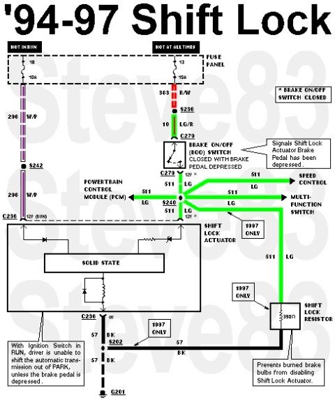
All ('94-up) vehicles are equipped with a shift interlock system. The shift interlock system prevents the shifting from PARK (the ignition key is in the RUN position) unless the service brake is depressed. The shift interlock system consists of a shift lock actuator mounted at the base of the steering column. If the ignition key is in the RUN position, the shift lock actuator continually runs unless the brake is depressed.
See also:
Part of 1980-1986 Ford Bronco Wiring Diagrams
This document is a wiring diagram for the shift lock (brake-shift interlock) system on 1994-1997 Ford trucks, drawn/annotated by Steve83. It shows two power feeds from the fuse panel: fuse 18 (10A, hot in run) supplying circuit 296 W/P to the Shift Lock Actuator via splice S242 and connector C236, and fuse 13 (15A, hot at all times) supplying circuit 383 R/W through splice S236 and circuit 10 LG/R to the Brake On/Off (BOO) switch at connector C279. When the brake pedal is depressed the BOO switch closes, sending 12V on circuit 511 LG through splice S240 to the Powertrain Control Module (PCM), Speed Control, Multi-Function Switch, and the Shift Lock Actuator. The actuator contains a solid-state module and grounds through circuit 57 BK at splice S202 to G201. A 390-ohm Shift Lock Resistor (1997 only) is shown, noted to prevent burned brake bulbs from disabling the Shift Lock Actuator. A callout explains that with the ignition in RUN, the driver cannot shift the automatic transmission out of PARK unless the brake pedal is depressed. Wire circuit numbers, colors, splices, and connectors are all labeled.
This document covers 1994-1997, which may differ from this 1983 Ford Bronco.
Is this accurate? Sign in to help verify it.
Frequently asked questions
- Which fuses power the 1994-1997 Ford shift lock system?
- Fuse 18 (10A, hot in run) feeds circuit 296 W/P to the Shift Lock Actuator, and fuse 13 (15A, hot at all times) feeds circuit 383 R/W to the Brake On/Off (BOO) switch.
- What wire signals the shift lock actuator that the brake pedal is depressed?
- Circuit 511 LG (light green) from the Brake On/Off (BOO) switch, which closes with the brake pedal depressed, signals the Shift Lock Actuator. It also feeds the PCM, Speed Control, and Multi-Function Switch through splice S240.
- What is the shift lock resistor and what does it do?
- It is a 390-ohm resistor used on 1997 models only, wired between circuit 511 LG and ground circuit 57 BK. It prevents burned brake bulbs from disabling the Shift Lock Actuator.
- Why can't I shift out of PARK without pressing the brake?
- Per the diagram's note, with the ignition switch in RUN the driver is unable to shift the automatic transmission out of PARK unless the brake pedal is depressed.
- Where does the shift lock actuator ground?
- Through circuit 57 BK via connector C236 and splice S202 to ground G201.






No comments yet.