Home/
Registry/
Ford/
Bronco/
1978-1979/
“buyers guide”/
Photo
supermotors.net/registry/media/765723
Ford Steering Column Installation Diagram & Disassembly - E-100-E-350 (13-06-7)

Reference · 1978-1979 BroncoAll 79 exploded parts diagrams
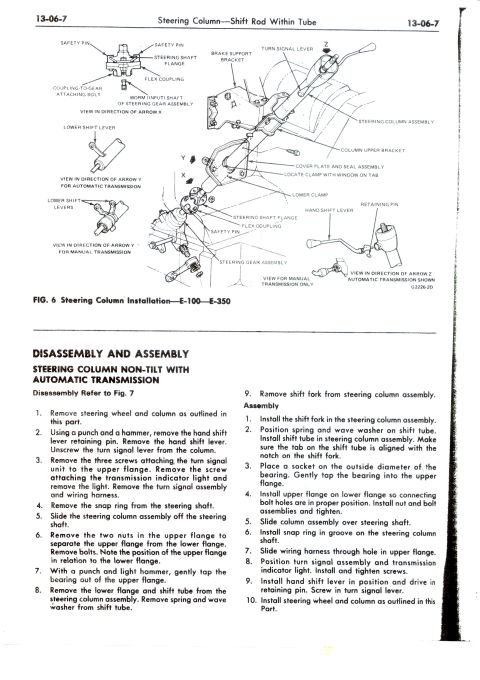
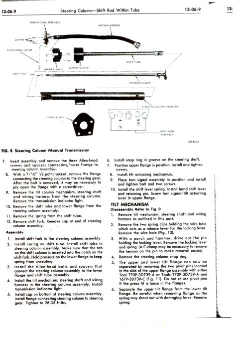
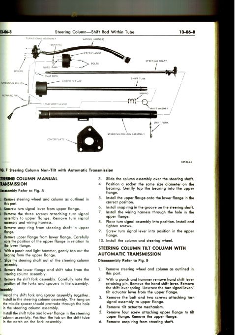
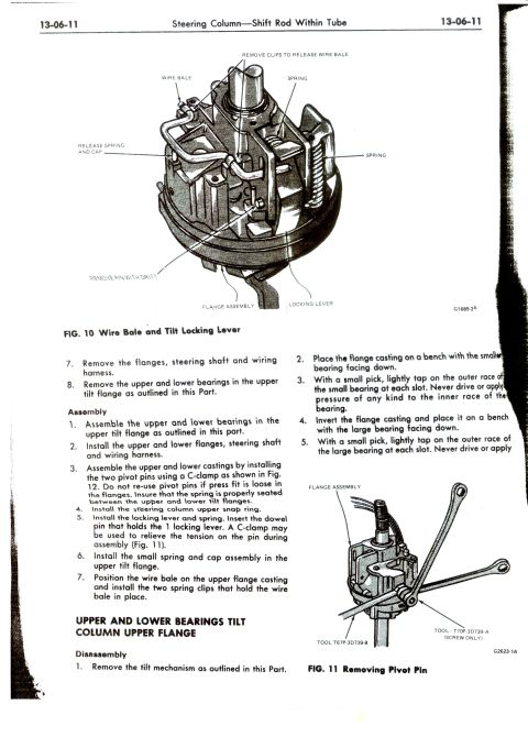
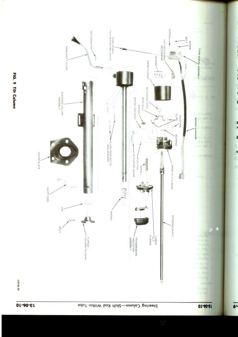
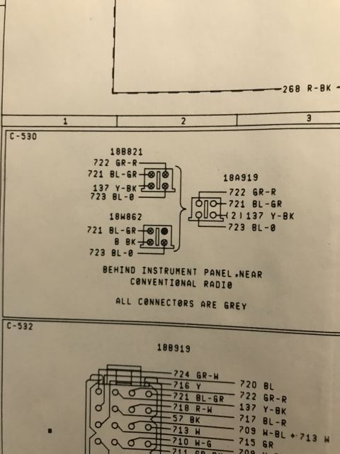
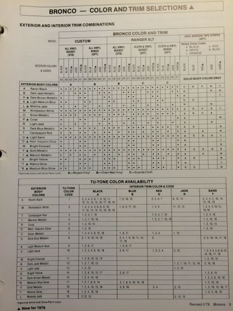
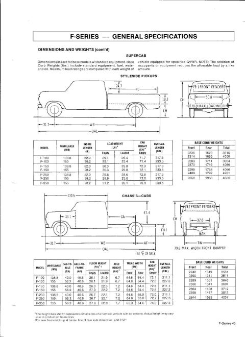
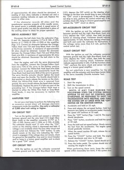
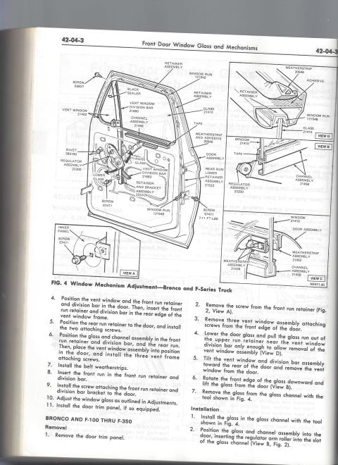
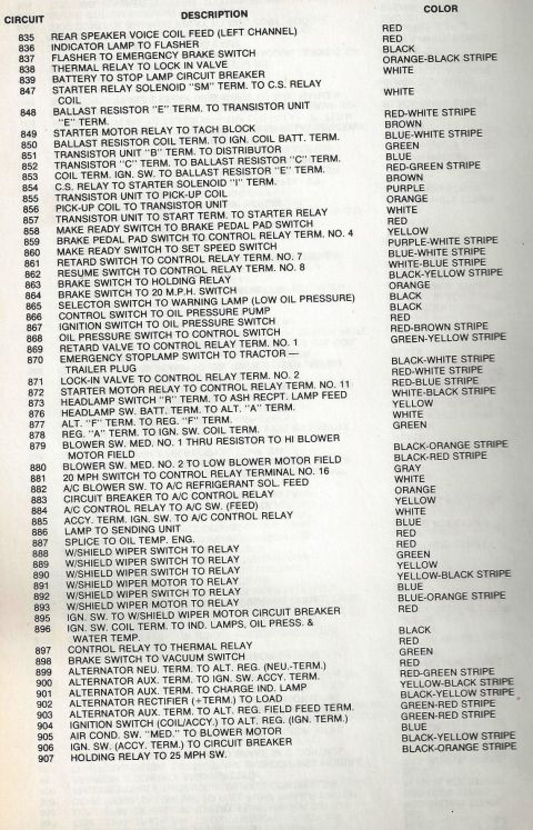
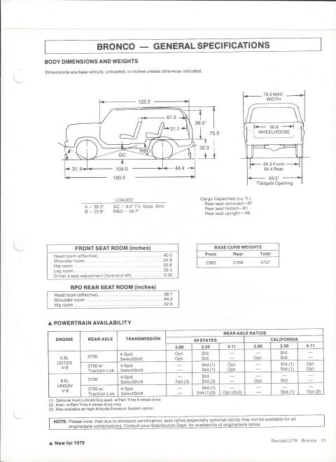
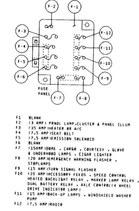


Ford service-manual exploded view and disassembly/assembly procedure for the non-tilt steering column with column shift on E-100 through E-350 vans (automatic and manual transmission).
Part of 1978-1979 Ford Bronco Exploded Parts Diagrams
This is page 13-06-7 of a Ford factory shop manual section titled 'Steering Column: Shift Rod Within Tube.' The upper half contains Fig. 6, an exploded/installation diagram of the steering column for E-100 through E-350 Econoline models, with labeled callouts including the safety pins, steering shaft flange, flex coupling, coupling-to-gear attaching bolt, worm (input) shaft, brake support bracket, turn signal lever, steering column assembly, column upper bracket, cover plate and seal assembly, lower clamp, hand shift lever, retaining pin, and steering gear assembly. Detail views (arrows X, Y, Z) show the lower shift lever configurations for automatic and manual transmissions. The lower half provides step-by-step Disassembly and Assembly procedures for a non-tilt steering column with automatic transmission: nine disassembly steps (removing the steering wheel, hand shift lever retaining pin, turn signal unit, snap ring, upper/lower flanges, bearing, shift tube, spring, wave washer, and shift fork) and ten assembly steps in reverse order, including aligning the shift tube tab with the shift fork notch and seating the bearing into the upper flange with a socket. A reader can identify column components by name and follow the full column overhaul procedure.
Is this accurate? Sign in to help verify it.
Frequently asked questions
- What does Fig. 6 on page 13-06-7 show?
- Fig. 6 shows the steering column installation for E-100 through E-350 models, with callouts for the safety pins, steering shaft flange, flex coupling, brake support bracket, turn signal lever, column upper bracket, cover plate and seal assembly, lower clamp, hand shift lever, retaining pin, and steering gear assembly, plus detail views for automatic and manual transmission lower shift levers.
- How is the hand shift lever removed from the steering column?
- Using a punch and a hammer, remove the hand shift lever retaining pin, then remove the hand shift lever. The turn signal lever unscrews from the column.
- How do you remove the turn signal unit from the column?
- Remove the three screws attaching the turn signal unit to the upper flange, remove the screw attaching the transmission indicator light and remove the light, then remove the turn signal assembly and wiring harness.
- How is the bearing installed in the upper flange during assembly?
- Place a socket on the outside diameter of the bearing and gently tap the bearing into the upper flange.
- What alignment must be checked when installing the shift tube?
- Make sure the tab on the shift tube is aligned with the notch on the shift fork when installing the shift tube in the steering column assembly.






No comments yet.