Home/
Registry/
Ford/
Bronco/
1992-1996/
“Buckin Bronco”/
Photo
supermotors.net/registry/media/1136389
Ford Bronco Backup Lamps Wiring Diagram 93-1 - Reverse Light Circuit
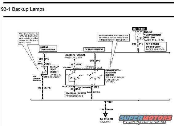
Wiring diagram for backup lamps showing backup lamp switch and park/neutral position switch circuits for manual and C6 transmissions.
This is page 93-1 of a Ford factory-style wiring diagram covering the Backup Lamps circuit. It shows how the backup (reverse) lamps receive power from fuse E (15A) in the engine compartment fuse box, which is hot in RUN (see Power Distribution, pages 13-4, 13-10). Power travels on circuit 298 (P/O wire). Two transmission variants are diagrammed: with a manual transmission, voltage passes through connector C166 to the backup lamp switch, which closes in reverse and outputs on circuit 140 (BK/PK). With the C6 automatic transmission, voltage goes through connector C127 into the park/neutral position switch (switch testing detailed on page 149-11); the switch also interfaces with the starting system via circuits 33 W/PK (12V start) and 32 R/LB (12V P or N), referenced to starting system pages 20-2 and 20-4. In reverse, the switch outputs on circuit 140 BK/PK. Both branches join and pass through connector C103, continuing on circuit 140 BK/PK to splice S116 on page 93-3, where the backup lamps themselves are shown. Callout notes explain that in REVERSE each switch provides voltage to illuminate the backup lamps.
Is this accurate? Sign in to help verify it.
Frequently asked questions
- What fuse powers the backup lamps in this diagram?
- Fuse E, a 15A fuse in the engine compartment fuse box, which is hot in RUN. See Power Distribution on pages 13-4 and 13-10.
- What wire color and circuit feed the backup lamp switch?
- Circuit 298, a P/O (pink/orange) wire, supplies 12V in RUN; the switch output is circuit 140, BK/PK (black/pink).
- How do the backup lamps work with a manual transmission?
- With the transmission in REVERSE, the backup lamp switch (through connector C166) closes and provides voltage on circuit 140 BK/PK to illuminate the backup lamps.
- How do the backup lamps work with a C6 automatic transmission?
- The park/neutral position switch (connector C127) directs voltage to the backup lamps when in REVERSE, outputting on circuit 140 BK/PK. Switch testing is on page 149-11.
- Where does the backup lamp circuit continue after this page?
- Circuit 140 BK/PK passes through connector C103 and goes to splice S116 on page 93-3.
Comments
More from this build














No comments yet.