Home/
Registry/
Hyundai/
Genesis Coupe/
2010-2016/
“Coupe”/
Photo
supermotors.net/registry/media/1142119
Hyundai Genesis Coupe Heater Core Removal - Service Manual Page HA-36
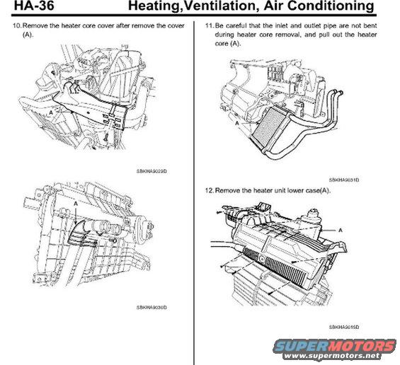
Service procedure page detailing heater core cover and heater unit removal steps with labeled figures.
Part of 2010-2016 Hyundai Genesis Coupe Service Procedures
This is page HA-36 from a Hyundai factory service manual's Heating, Ventilation, Air Conditioning (HA) section, showing part of the heater core / heater unit disassembly procedure. The page contains steps 10 through 12 of the removal sequence. Step 10 instructs removal of the heater core cover after removing cover (A), supported by two illustrations (reference codes SBKHA9029D and SBKHA9030D). Step 11 cautions the technician not to bend the inlet and outlet pipes during heater core removal, then to pull out the heater core (A), illustrated with an exploded-style drawing of the core and its pipes (SBKHA9031D). Step 12 shows removal of the heater unit lower case (A), with arrows indicating fastener locations (SBKHA9015D). A reader learns the correct sequence for accessing and extracting the heater core from the heater unit and the key caution about pipe damage. The page is one of a multi-page heater unit procedure (companion pages exist in the same upload set). No torque values, part numbers, or model/year applicability statements are visible on this page; identification comes from the uploader's attribution to a 2010 Hyundai Genesis Coupe.
Is this accurate? Sign in to help verify it.
Frequently asked questions
- How do I remove the heater core according to this procedure?
- After removing the cover (A) and the heater core cover (steps 10), be careful that the inlet and outlet pipes are not bent, then pull out the heater core (A) as shown in step 11.
- What caution is given when removing the heater core?
- The document warns to be careful that the inlet and outlet pipe are not bent during heater core removal.
- What step comes after pulling out the heater core?
- Step 12 instructs removing the heater unit lower case (A).
- What manual section is this page from?
- Page HA-36 of the Heating, Ventilation, Air Conditioning section, showing steps 10-12 with illustration codes SBKHA9029D, SBKHA9030D, SBKHA9031D, and SBKHA9015D.
Comments
More from this build









No comments yet.