Home/
Registry/
Ford/
Mustang/
1964-1973/
“Race Car Tope”/
Photo
supermotors.net/registry/media/1161895
Ford 427 Medium-Riser Induction System & 4V Intake Manifold Development
Reference · 1964-1973 MustangAll 16 manual pages
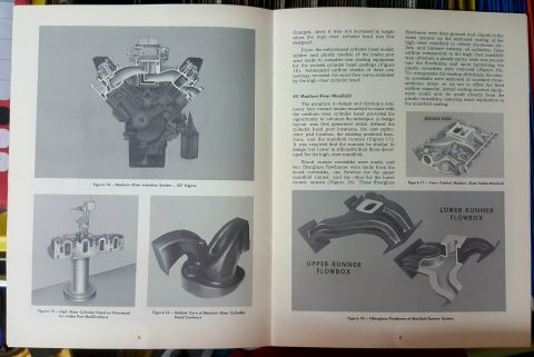
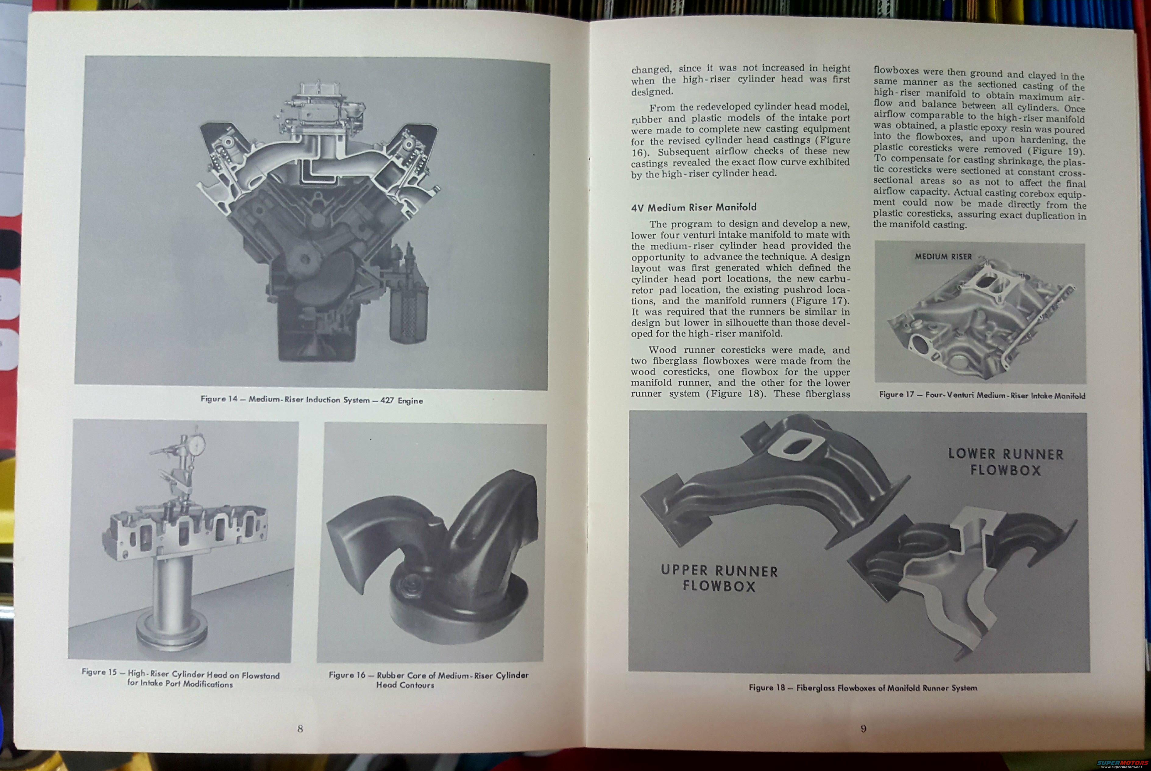
Manual page on medium-riser intake manifold development with photographs of manifolds, foundry cores, and fiberglass flowboxes.
Part of 1964-1973 Ford Mustang Manual Pages
This is a two-page spread (pages 8-9) from a Ford engineering publication describing the design and development of the medium-riser induction system for the 427 engine. Page 8 contains three photographs: Figure 14 shows a cutaway of the medium-riser induction system on the 427 engine; Figure 15 shows a high-riser cylinder head mounted on a flowstand for intake port modifications; and Figure 16 shows a rubber core of the medium-riser cylinder head contours. Page 9 text explains how rubber and plastic models of the intake port were used to create casting equipment for revised cylinder head castings, with airflow checks confirming the new castings matched the high-riser head's flow curve. A section titled '4V Medium Riser Manifold' details development of a new, lower four-venturi intake manifold: design layout defining port, carburetor pad, and pushrod locations; wood runner coresticks; fiberglass flowboxes for upper and lower runners (Figure 18); grinding and claying to maximize and balance airflow; pouring plastic epoxy resin to make coresticks (Figure 19); and sectioning the coresticks to compensate for casting shrinkage. Figure 17 pictures the finished four-venturi medium-riser intake manifold. Readers learn Ford's flowbox/corestick development methodology for high-performance 427 intake manifolds.
Is this accurate? Sign in to help verify it.
Frequently asked questions
- What engine is the medium-riser induction system shown for?
- Figure 14 shows the Medium-Riser Induction System for the Ford 427 engine.
- How was the 4V medium-riser intake manifold developed?
- A design layout defined cylinder head port locations, the new carburetor pad location, existing pushrod locations, and manifold runners. Wood runner coresticks were made, then two fiberglass flowboxes (one for the upper manifold runner, one for the lower runner system), which were ground and clayed to obtain maximum airflow and balance between all cylinders.
- How were the plastic coresticks made and why were they sectioned?
- Plastic epoxy resin was poured into the fiberglass flowboxes; after hardening, the plastic coresticks were removed. They were sectioned at constant cross-sectional areas to compensate for casting shrinkage without affecting final airflow capacity.
- What was required of the medium-riser manifold runners compared to the high-riser design?
- The runners had to be similar in design but lower in silhouette than those developed for the high-riser manifold.
- Did the revised cylinder head castings flow as well as the high-riser head?
- Yes: airflow checks of the new castings revealed the exact flow curve exhibited by the high-riser cylinder head.


No comments yet.