Home/
Registry/
Ford/
Mustang/
1964-1973/
“Race Car Tope”/
Photo
supermotors.net/registry/media/1161891
Ford 351 V8 Engine Design Features - Cylinder Block vs 302, Main Bearing Caps

Reference · 1964-1973 MustangAll 16 manual pages
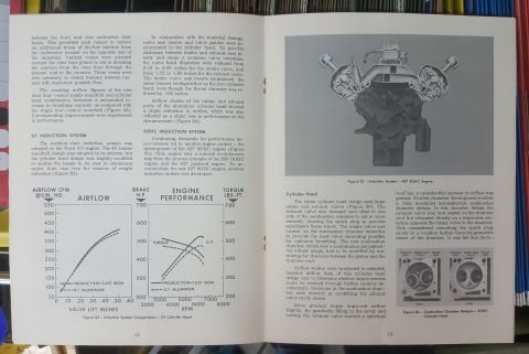
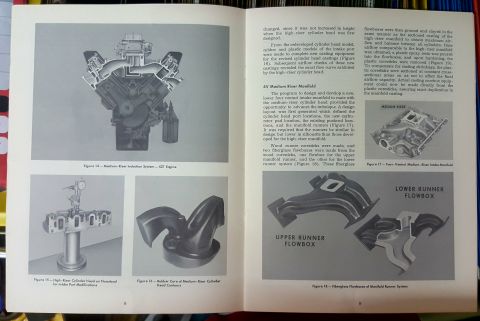
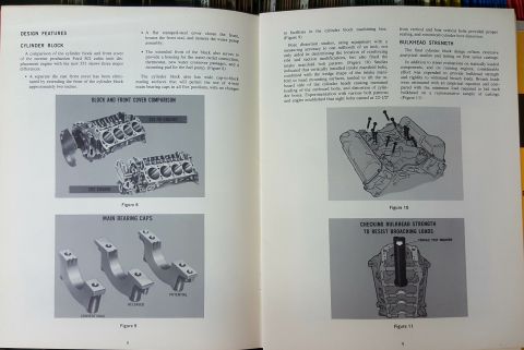
Manual page on cylinder block and bulkhead design features with photographs comparing engine blocks and main bearing caps.
Part of 1964-1973 Ford Mustang Manual Pages
This two-page spread (pages 8-9) from a Ford engineering reference booklet describes the design features of the cylinder block for the then-new Ford 351 cubic inch V8 engine, comparing it to the current production 302 cubic inch engine. Three major differences are listed: elimination of the separate die-cast front cover by extending the block front about two inches, use of a flat stamped-steel front cover housing the front seal and water pump, and integration of the water outlet, thermostat housing, water crossover passages, and fuel pump mounting pad into the extended block front. The text notes the 351 block has wide cap-to-block mating surfaces permitting 4-bolt main bearing caps in all five positions. Bore distortion studies (accurate to one millionth of an inch) determined reinforcing rib locations and the intake manifold bolt pattern: eight bolts canted at 22-1/2° from vertical plus four vertical bolts minimized bore distortion. A Bulkhead Strength section describes stress evaluations and broach-load testing of first-series castings. Illustrations include Figure 8 (block and front cover comparison, 351-4V vs. 302 engine), Figure 9 (conventional, released, and potential main bearing caps), Figure 10 (intake manifold bolt arrangement), and Figure 11 (checking bulkhead strength with a tensile test machine).
Is this accurate? Sign in to help verify it.
Frequently asked questions
- What are the major differences between the Ford 302 and 351 cylinder blocks?
- Three major differences: the separate die-cast front cover was eliminated by extending the front of the 351 block about two inches; a flat stamped-steel cover closes the front, houses the front seal, and mounts the water pump; and the extended block front houses the water outlet connection, thermostat, new water crossover passages, and a fuel pump mounting pad.
- Can the Ford 351 block use 4-bolt main bearing caps?
- Yes. The cylinder block has wide cap-to-block mating surfaces that permit the use of 4-bolt main bearing caps in all five positions, with no changes to the block machining line facilities.
- What intake manifold bolt pattern minimized cylinder bore distortion on the 351?
- Experimentation established that eight bolts canted at 22-1/2° from vertical plus four vertical bolts provided proper sealing and minimized cylinder bore distortion.
- How was bulkhead strength verified on the 351 block?
- Broach loads were estimated with an empirical equation and compared with the minimum load required to fail each bulkhead on a representative sample of castings, checked with a tensile test machine (Figure 11).
- What types of main bearing caps are shown in Figure 9?
- Three types are illustrated: conventional, released, and potential main bearing caps.

No comments yet.