1994-1996 Ford Bronco/F-150 Airbag Circuit Wiring Diagram - SRS Sensors & Pins

'94-96 Bronco/F-series (under 8500GVWR) Airbag Circuit & Codes
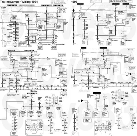
IF THE IMAGE IS TOO SMALL, click it.
The air bag diagnostic monitor (14B056) continually monitors all supplemental air bag restraint system components and wiring connections for possible faults in the system. If the air bag diagnostic monitor detects a fault in the supplemental air bag restraint system when the key is in RUN, a diagnostic trouble code will be displayed on the air bag indicator, located in the instrument cluster (10849). Performing system diagnostics is the main purpose of the air bag diagnostic monitor.
Note: The air bag diagnostic monitor does NOT deploy the air bag in the event of a crash.
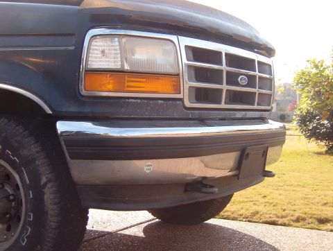
The LH and RH primary crash sensors (attached to the core support behind the grille) are hard wired to the air bag; therefore, the LH and RH primary crash sensors and RH safing sensor (at the base of the RH B-pillar) determine when to deploy the air bag.
Features and functions of the air bag diagnostic monitor are described below.
* The air bag diagnostic monitor illuminates the air bag indicator for approximately six seconds when the key is in RUN and then turns the indicator off. This shows that the air bag indicator is operational. If the air bag indicator does not illuminate or the indicator stays on or flashes at any time, a fault has been detected by the air bag diagnostic monitor.
* Diagnostic trouble codes may not be displayed for approximately 30 seconds after the key is placed in RUN. This is the amount of time the air bag diagnostic monitor requires to perform all tests and verify system faults, if present.
* Each diagnostic trouble code (a series of flashes and pauses of the air bag indicator) represents a two-digit number. Each diagnostic trouble code is always displayed at least twice. For example, a diagnostic trouble code 32 is displayed as three flashes, followed by a one-second pause, then two flashes, followed by a three-second pause.
* If a system fault is present and the air bag indicator is malfunctioning (bulb burned or removed), an audible tone will be heard, indicating that system service is required. The tone is a series of five sets of five beeps. This does not indicate a diagnostic trouble code 55. If the tone is heard, the air bag indicator is inoperative and a system fault that requires service is present.
CAUTION: The thermal fuse does not blow (open) because of excessive current flowing through it. DO NOT attempt to jumper out the thermal fuse with a circuit breaker or any other type of fuse.
* If a fault exists that makes unwanted air bag deployment possible, the air bag diagnostic monitor has an internal thermal fuse that will blow (open) automatically. This removes all power to the air bag deployment circuit.
* The air bag indicator will flash the appropriate diagnostic trouble code to indicate the suspect circuit. If the indicator is malfunctioning the tone will be heard.
* Diagnostic trouble codes are prioritized numerically so if two or more different faults occur at the same time, the fault having the highest priority will be displayed first. After that fault has been corrected, the next highest priority fault will be displayed.
* The air bag diagnostic monitor includes an internal backup power supply. This feature provides sufficient backup power to deploy the air bag in the event the battery or battery cables are damaged in an accident before safing and primary crash sensors close. The backup power supply will deplete its stored energy approximately one minute after the positive battery cable is disconnected.
Airbag DIagnostic Monitor (ADM) Light Flash Code (LFC) Priority Table
Tone (5 Beeps Repeated 4 Times): Air Bag Indicator Open Circuit with Stored Fault Code(s)
No Air Bag Indicator (Dash Light Out): Inoperative Indicator Circuit or No Battery Voltage to ADM
Continuous Air Bag Indicator: ADM Disconnected or Inoperative
12: Low Battery Voltage
13: Air Bag Circuit Shorted to Ground
14: Front Air Bag Sensor and Bracket Circuit Shorted to Ground
21: Rear Air Bag Sensor and Bracket Not Mounted to Vehicle Properly
22: Rear Air Bag Sensor and Bracket Output Circuit Shorted to Battery Voltage
23: Rear Air Bag Sensor and Bracket Circuit Input Feed/Return Circuit Open
24: Rear Air Bag Sensor and Bracket Output Feed/Return Circuit Open
32: Driver Side Air Bag Circuit High Resistance or Open
34: Driver Side Air Bag Circuit Low Resistance or Shorted
41: RH Front Air Bag Sensor and Bracket Feed/Return Circuit Open
42: LH Front Air Bag Sensor and Bracket Feed/Return Circuit Open
44: RH Front Air Bag Sensor and Bracket Not Mounted to Vehicle Properly
45: LH Front Air Bag Sensor and Bracket Not Mounted to Vehicle Properly
51: ADM Internal Thermal Fuse Blown Due to Intermittent Short to Ground
52: Backup Power Supply Voltage Boost Fault
53: Front Air Bag Sensor and Bracket Circuits Resistance to Ground or ADM Fault
Rapid Continuous Flashing (No Fault Code): All Primary Air Bag Sensors Disconnected
See also:
http://www.bbbind.com/free_tsb.html .
.  .
.  .
.  .
. 
This document covers 1994-1996, which may differ from this 1983 Ford Bronco.
Is this accurate? Sign in to help verify it.
Frequently asked questions
- What fuses power the 1994-96 Ford air bag system?
- Three 10A fuses: fuse panel position 4 (hot at all times, circuit 937 R/W), position 5 (hot in run, circuit 296 W/P), and position 17 (hot in start or run, circuit 640 R/Y to the air bag indicator).
- What is the resistance of the driver air bag and clockspring sliding contact?
- The driver air bag is 1.0 Ω, and the air bag sliding contact winding is 0.25-0.5 Ω per leg.
- How many crash sensors must trigger to deploy the air bag?
- At least two of the three sensors (LH front, RH front primary crash sensors, and the rear safing sensor) must be activated to inflate the air bag.
- Why does the air bag warning lamp light when the diagnostic monitor is disconnected?
- The harness connectors contain shorting-bar inserts; pins 4 & 5 are shorted together when disconnected, which energizes the air bag warning lamp. Pins 2 & 3 and 10 & 11 are also shorted to prevent static discharge into the air bag.
- What must be done before checking circuits 624 or 617 for a short to ground?
- A shorting bar is in the gray diagnostic monitor harness connector; the plastic wedge in the gray connector must be removed before checking circuit 624 or 617 for a short to ground.
Comments
More from this build








No comments yet.