1992-Up Ford Multifunction Switch (MFS) Testing - Terminal Pinout & Ohm Values

Reference · 1980-1986 BroncoAll 92 wiring diagrams
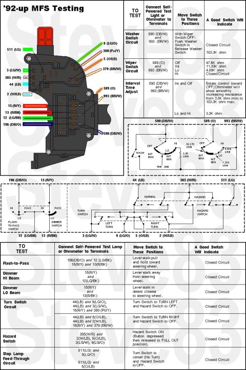
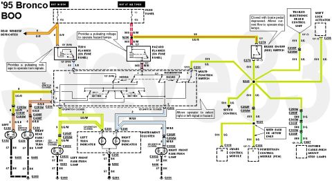






MFS Testing '92-up
IF THE IMAGE IS TOO SMALL, click it.
Upper Connector Motorcraft WPT-611
Lower Connector Motorcraft WPT-179
Use these photos for access to the MFS: .
. 
Use these to repair it:
See also: .
.  .
.  .
. 
--------------------------------------------------------------------------------------------------
TSB 02-17-6: LAMP - BRAKE - INADVERTENT DISABLING OF BRAKE SHIFT INTERLOCK
Publication Date: AUGUST 22, 2002
Article 01-18-1 is being republished in its entirety to update the model year coverage and vehicle line applications.
FORD:
1992-1993 FESTIVA
1992-1994 TEMPO
1992-1997 THUNDERBIRD
1992-2003 CROWN VICTORIA, ESCORT, MUSTANG, TAURUS
1993-1997 PROBE
1994-1997 ASPIRE
1995-2000 CONTOUR
2002-2003 THUNDERBIRD
1992-1997 AEROSTAR
1992-2003 E SERIES
1993-1997 F SUPER DUTY
1994-1996 BRONCO
1994-1997 F-250, F-350
1994-2003 F-150
1995-2003 EXPLORER, RANGER, WINDSTAR
1997-2003 EXPEDITION
1998-1999 F-250 LD
1999-2003 SUPER DUTY F SERIES
2000-2003 EXCURSION, EXPLORER SPORT
2001-2003 ESCAPE, EXPLORER SPORT TRAC
LINCOLN:
1992-2003 CONTINENTAL, TOWN CAR
1993-1998 MARK VIII
2000-2003 LS
1998-2003 NAVIGATOR
MERCURY:
1992-1994 TOPAZ
1992-1997 COUGAR
1992-1999 TRACER
1992-2003 SABLE
1993-2003 GRAND MARQUIS
1994 CAPRI
1995-2000 MYSTIQUE
1999-2003 COUGAR
1993-2002 VILLAGER
1997-2003 MOUNTAINEER
ISSUE: Corporate, municipal, or police fleets may have had their Ford Motor Company vehicle modified to flash the brake lamps whenever the "police lights" or other aftermarket lights are turned on. These added "police lights" have the potential to disable the brake shift interlock system. The brake shift interlock feature prevents the vehicle from being shifted from park unless the brake pedal is depressed. Disabling of the brake shift interlock feature may enable the operator to inadvertently apply the accelerator instead of the brake pedal when shifting from Park to Drive or Reverse gears.
ACTION: As appropriate, dealers should advise owners (including corporate, municipal, and police agencies) that any vehicle that has been modified with a connection to the brake circuit, or that electrically interfaces with the brake lamps in that manner, should be disconnected IMMEDIATELY and the emergency lighting system should be modified in a manner that does not interfere with normal service operation or the brake shift interlock. In addition, if the high-mount stop lamp flashes when the "police lights" are on, the modification does not conform with the Federal Motor Vehicle Safety Standards (FMVSS) 108 which requires that the high-mount stop lamp only illuminate when applying the brakes.
Installation of warning lights should only be performed with a completely separate electrical system, without connection to any existing vehicle wiring. Connection of aftermarket electrical equipment into the brake lamp circuit or any other circuit which is connected to the Powertrain Control Module (PCM), anti-lock brake computer, air bag system, or any other vehicle system, will cause vehicle malfunction.
OTHER APPLICABLE ARTICLES: NONE
SUPERSEDES: 01-18-1
--------------------------------------------------------------------------------------------
TSB 02-13-6: BRAKES - STOPLAMPS INOPERATIVE - SERVICE REPAIR KIT FOR BRAKE PEDAL POSITION SWITCH WIRING CONNECTOR
ELECTRICAL - TRANSMISSION SHIFT INTERLOCK INOPERATIVE - SERVICE REPAIR KIT FOR BRAKE PEDAL POSITION SWITCH WIRING CONNECTOR
Publication Date: JUNE 25, 2002
FORD: 1998-2002 CROWN VICTORIA
LINCOLN: 1998-2002 TOWN CAR
MERCURY: 1998-2002 GRAND MARQUIS
ISSUE: The Brake Shift Interlock may be inoperative on some vehicles, not allowing the operator to move the shift lever from the Park position. Stop Lamp operation may also be affected. This may be caused by a deformed Brake Pedal Position Switch electrical connector.
ACTION: Restore Brake Pedal Position Switch operation by installing an updated electrical connector and pigtail. Refer to the following Service procedure for details.
SERVICE PROCEDURE
1. Verify the condition.
2. Remove LH instrument panel insulator. Refer to Workshop Manual Section 501-05.
3. Inspect the Brake Pedal Position Switch electrical connector (2000/2001 - C2002: 2002 - C27 for deformation. Refer to Wiring Diagrams, Section 90 for additional details.
4. If no deformation is found, refer to Workshop Manual, Sections 307-05 & 417-01, for normal diagnostic information.
5. If deformation is found, continue with the following procedure.
6. Disconnect the battery ground cable.
7. Disconnect the Brake Pedal Position Switch electrical connector.
8. Remove the deformed connector by cutting off 4 inches of wire from the harness.
9. Strip approximately 1/4" from the remaining harness and twist the end of each wire.
10. Obtain the repair kit part number 2W1Z-14A411-AAA.
11. The repair kit pigtail wiring comes in 1 piece with connectors.
12. Strip approximately 1/4" of insulation from the repair pigtail and twist the end of each wire.
13. Since the switch is polarity sensitive, match evenly the wire color (LG light green to LG, LG/RD light green with red strip with LG/RD).
14. Use crimp connectors that are found in the repair kit.
15. Evenly position the crimp connectors over the wire repair.
16. To crimp the connectors, use the proper wire crimp tool.
17. Use a heat gun to heat the repaired area until adhesive flows out of both ends of the heat shrink.
18. Reconnect the Brake Pedal Position Switch.
19. Replace the LH instrument panel insulator.
20. Reconnect battery ground cable.
21. Test and verify the Brake Pedal Position Switch operates properly.
PART NUMBER: 2W1Z-14A411-AAA
PART NAME: Repair Kit - Brake Pedal Position Switch Electrical Connector
OTHER APPLICABLE ARTICLES: NONE
WARRANTY STATUS:: Eligible Under The Provisions Of Bumper To Bumper Warranty Coverage
OPERATION: 021306A
DESCRIPTION: Replace Brake Pedal Position Switch Electrical Connector
TIME: 0.4 Hr.
Part of 1980-1986 Ford Bronco Wiring Diagrams
This document covers 1992-up, which may differ from this 1983 Ford Bronco.
Is this accurate? Sign in to help verify it.
Frequently asked questions
- What resistance should a good Ford multifunction switch show in each wiper position?
- Testing between terminals 589 (O) and 993 (BR/W): Off = 47.6K ohm, Int = 11.33K ohm, Lo = 4.08K ohm, Hi = closed circuit.
- How do I test the washer switch circuit on the multifunction switch?
- With the wiper switch OFF, connect an ohmmeter or self-powered test light to terminals 590 (DB/W) and 993 (BR/W). Pushing the washer switch in should show a closed circuit; releasing it should show 103.3K ohm.
- How is the interval (delay) wiper adjustment tested?
- Across terminals 590 (DB/W) and 993 (BR/W) with the switch between Int and Off, rotating the control toward OFF should show smoothly increasing resistance from 3.3K ohm minimum to 103.3K ohm maximum. Between Lo and Hi it should read 3.3K ohm.
- Which terminals verify the flash-to-pass function?
- Connect the tester to 196 (DB/O) and 12 (LG/BK), and to 15 (R/Y) and 13 (R/BK). Pulling and holding the lever stalk toward the steering wheel should show a closed circuit.
- How do I test the turn signal circuits on this switch?
- For left turn (hazard OFF): 44(LB) and 9(LG/O), 44(LB) and 3(LG/W), 15(R/Y) and 380(PU/Y) should all show closed circuit. For right turn: 44(LB) and 5(O/LB), 44(LB) and 2(W/LB), 15(R/Y) and 379(BR/W) should show closed circuit.






No comments yet.