Home/
Registry/
Ford/
Bronco/
1980-1986/
“That dirty old truck”/
Photo
supermotors.net/registry/media/1172086
1996 Ford F-Series/Bronco EEC/PCM Connector Pinout Diagram: 4.9L 5.0L 5.8L

Reference · 1980-1986 BroncoAll 92 wiring diagrams
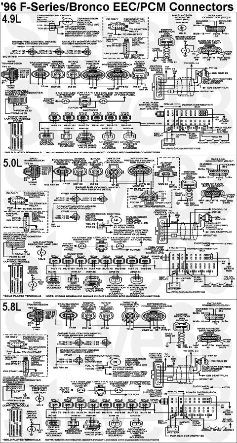






'96 F-Series & Bronco EEC-V PCM Connector Faces & Pinouts
IF THE IMAGE IS TOO SMALL, click it.
See also:
 .
.  .
. 
Part of 1980-1986 Ford Bronco Wiring Diagrams
This document is a wiring/connector reference diagram titled "'96 F-Series/Bronco EEC/PCM Connectors," covering the 4.9L inline six, 5.0L V8, and 5.8L V8 engines in 1996 Ford F-Series trucks and Broncos. For each engine, it illustrates the physical shapes and pinouts of the harness connectors that plug into the Powertrain Control Module (PCM) system, with PCM pin numbers labeled at each connector. Components covered include the E4OD transmission connector (TFT 37, CCS 53, TCC 54, SS1 27, SS2 1, EPC 81), the 4R70W transmission (5.0L), transmission range sensor, ECT, IAT, TP, DPFE EGR, knock sensor (4.9L), output shaft speed sensor (5.0L), heated oxygen sensors (fuel control and catalyst monitor), misfire detection sensor, MAF sensor, data link connector (DLC), ignition control module, camshaft position sensor, PSOM, fuel injectors (INJ-1 through INJ-8 with pin numbers), IAC, EVR, VMV, AIRB/AIRD solenoids, park/neutral or clutch pedal position switches, brake on/off switch, MIL, transmission control switch, fuel pump/inertia switch circuit, and the power distribution box with EEC, fuel pump, and WAC relays. Footnotes indicate gold-plated terminals and that pinouts are shown looking into the harness connectors.
This document covers 1996, which may differ from this 1983 Ford Bronco.
Is this accurate? Sign in to help verify it.
Frequently asked questions
- What engines does this 1996 Ford EEC/PCM connector diagram cover?
- It covers the 4.9L, 5.0L, and 5.8L engines for '96 F-Series trucks and Broncos, with a separate connector layout section for each engine.
- What are the PCM pin numbers for the fuel injectors?
- INJ-1 pin 75, INJ-2 pin 101, INJ-3 pin 74, INJ-4 pin 100, INJ-5 pin 73, INJ-6 pin 99, and on V8 engines INJ-7 pin 72 and INJ-8 pin 98.
- What pins does the E4OD transmission connector use?
- The E4OD connector shows TFT 37, CCS 53, TCC 54, SS1 27, SS2 1, and EPC 81, plus VPWR 71/97 and SIG RTN 91.
- Which pins are used by the Data Link Connector (DLC)?
- The DLC shows chassis ground, ground (B-), BUS+ 16, BUS- 15, and FEPS 13.
- Are the connector pinouts shown from the harness side or module side?
- A note on each section states the wiring schematic shows pinouts looking into the harness connectors, and gold-plated terminals are marked with an asterisk.






No comments yet.