Home/
Registry/
Ford/
F-150/
1975-1979/
1978 Ford F-150/
Photo
supermotors.net/registry/media/129323
1978 Ford F-150 Alternator & Voltage Regulator Wiring Diagram - Wire Colors

Reference · 1975-1979 F-150All 10 wiring diagrams
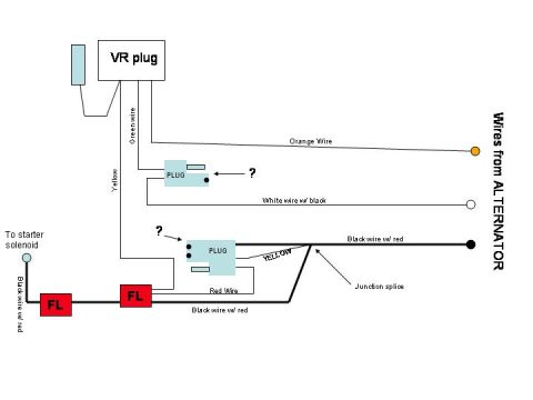
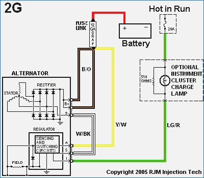
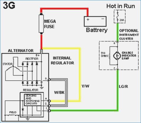
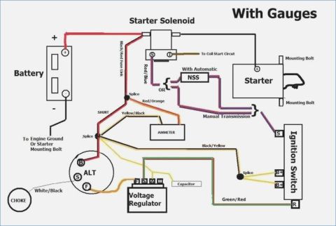

Wiring diagram of alternator and voltage-regulator circuits showing color-coded wires, plugs, and fusible links.
Part of 1975-1979 Ford F-150 Wiring Diagrams
This is a hand-drawn (computer-illustrated) wiring diagram showing the charging system wiring between a Ford voltage regulator (VR) plug and the alternator. On the left, the VR plug connects via a green wire and a yellow wire. On the right side, four wires come from the alternator: an orange wire, a white wire with black tracer, a black wire with red tracer, and a yellow wire. Two intermediate connectors labeled "PLUG" are shown, each marked with a question mark (indicating uncertain identification or terminal). The black wire with red tracer from the alternator passes through a junction splice, joins a yellow wire and a red wire at the second plug, and continues through two fusible links (labeled "FL" in red boxes) to the starter solenoid via a black wire with red tracer. The diagram helps a reader trace which alternator output wires route to the voltage regulator plug, where fusible links are located in the charging circuit, and how the main charge wire (black w/ red) reaches the starter solenoid. It is undated and does not state a specific model year, but it was uploaded for a 1978 Ford F-150 charging system reference.
Is this accurate? Sign in to help verify it.
Frequently asked questions
- What wire colors come from the alternator in this diagram?
- Four wires come from the alternator: an orange wire, a white wire with black tracer, a black wire with red tracer, and a yellow wire.
- What wire connects the charging circuit to the starter solenoid?
- A black wire with red tracer runs to the starter solenoid, passing through two fusible links (FL) along the way.
- How many fusible links are shown and where are they?
- Two fusible links (marked FL) are shown in the black wire with red tracer between the plug/junction splice area and the starter solenoid.
- What wires attach to the VR plug?
- The VR plug has a green wire and a yellow wire shown leaving it; the green wire connects toward the orange wire from the alternator.
- What happens at the junction splice?
- The black wire with red tracer from the alternator meets a yellow wire at the junction splice, which then feeds a plug along with a red wire before continuing to the fusible links and starter solenoid.



No comments yet.