Auto-Dimming Inside Rearview Mirror Wiring Diagram - Temp Sensor & Backup Lamp

Reference · 1975-1979 F-150All 10 wiring diagrams
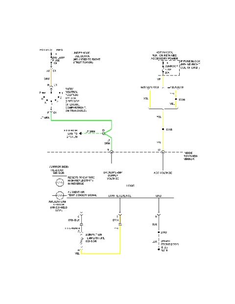



Wiring diagram showing mirror, sensor, and accessory circuits with color-coded wires and ground connections.
Part of 1975-1979 Ford F-150 Wiring Diagrams
This document is a wiring diagram (schematic) for an inside rearview mirror circuit, apparently an auto-dimming (electrochromic) mirror with an ambient air temperature display function. It shows power feeds from two fuse blocks: a Backup Lamp fuse in the underhood fuse block (mounted to the right strut tower), which is hot at all times and feeds through the park/neutral position switch (located on the left side of the engine compartment, on the transaxle) to provide a backup lamp supply voltage signal (light green wire, pin 9) to the mirror; and a 20A Sunroof fuse in the I/P fuse block (behind the right side of the dash), hot in accessory, run, or retained accessory power, providing ACC voltage on a yellow wire (pin 10), with splice variations for with/without sunroof (splices S334, S395). The mirror contains a headliner-side sensor and a windshield-side ambient light sensor, with a note that the mirror resets to daytime high reflectivity in reverse. It also shows an ambient air temperature sensor circuit (signal, low reference, and ground wires) with grounds G300 and G305 at the right front door sill. Wire colors shown include orange, light green, yellow, dark green, purple, and black.
Is this accurate? Sign in to help verify it.
Frequently asked questions
- What fuse powers the inside rearview mirror's accessory voltage in this diagram?
- The 20A Sunroof fuse in the I/P fuse block (located behind the right side of the dash), which is hot in accessory, run, or retained accessory power; it feeds the mirror on a yellow wire at pin 10.
- Where does the backup lamp supply voltage to the mirror come from?
- From the Backup Lamp fuse in the underhood fuse block (mounted to the right strut tower), through the park/neutral position switch on the transaxle, then on a light green wire to pin 9 of the inside rearview mirror.
- What happens to the auto-dimming mirror when the vehicle is in reverse?
- The diagram notes the mirror 'resets to daytime high reflectivity in reverse.'
- Where are the ground points for the mirror/temperature sensor circuit?
- The ground circuit (black wire) goes to splice/ground G300 and then to G305 at the right front door sill.
- What wire colors are used for the ambient air temperature sensor circuit?
- The signal wire is green/black (light green/black), the low reference is dark green transitioning to purple, and the sensor connects with a yellow wire; the mirror ground is black.





No comments yet.