Home/
Registry/
Ford/
F-150/
1975-1979/
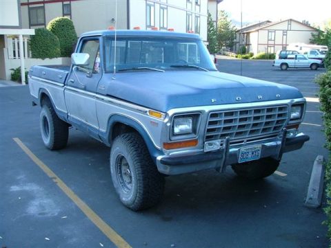
1979 Ford F-150/
Photo
supermotors.net/registry/media/1020234
Ford Power Window Wiring Diagram - Dash & Key Switch, Motor Wire Colors
Reference · 1975-1979 F-150All 10 wiring diagrams
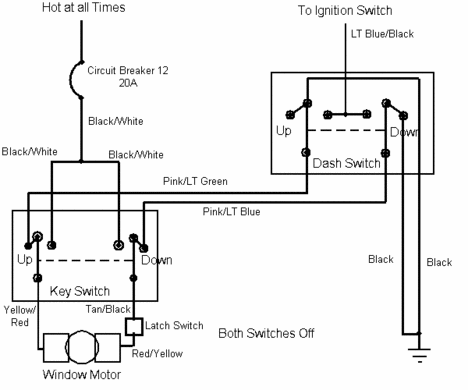


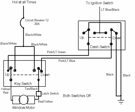
Wiring diagram of a power window circuit showing key switch, dash switch, latch and motor with labeled color-coded wires.
Part of 1975-1979 Ford F-150 Wiring Diagrams
This document is a power window wiring circuit diagram showing the electrical path for a single window motor controlled by two switches. Power comes from a source that is 'Hot at all Times' through Circuit Breaker 12 (20A) on a Black/White wire, which feeds a Key Switch (with Up and Down positions). A Dash Switch, also with Up and Down positions, receives power from the ignition switch via a LT Blue/Black wire. The two switches are interconnected by Pink/LT Green and Pink/LT Blue wires. From the Key Switch, Yellow/Red and Tan/Black wires lead toward the window motor; a Latch Switch is in series via a Red/Yellow wire before the Window Motor. Both Black wires from the Dash Switch run to a chassis ground. The diagram is drawn with 'Both Switches Off,' showing the at-rest state of the circuit. A reader can learn the wire color codes for each segment of the circuit, the circuit breaker number and amperage rating (Circuit Breaker 12, 20A), the switch arrangement (key-operated switch and dash switch controlling the same motor), and how the latch switch is wired in the motor feed path. No year, make, or model is stated on the document itself.
Is this accurate? Sign in to help verify it.
Frequently asked questions
- What circuit breaker protects this window motor circuit and what is its rating?
- Circuit Breaker 12, rated at 20A, fed from a source that is hot at all times.
- What wire color feeds the dash switch from the ignition switch?
- A LT Blue/Black wire runs from the ignition switch to the dash switch.
- What wire colors connect the dash switch to the key switch?
- Pink/LT Green and Pink/LT Blue wires connect the two switches.
- What wire colors go to the window motor?
- Yellow/Red and Tan/Black wires leave the key switch; a Red/Yellow wire runs from the Latch Switch to the Window Motor.
- In what state are the switches shown in this diagram?
- The diagram is drawn with both switches off (at rest).




No comments yet.