Home/
Registry/
Ford/
F-150/
1975-1979/
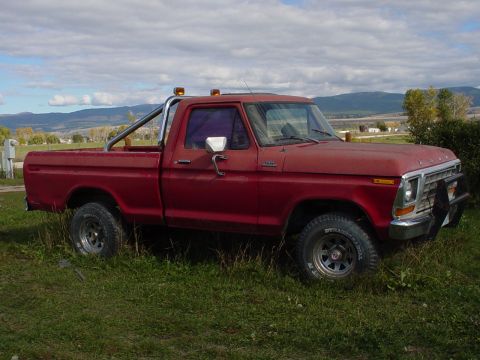
1979 Ford F-150/
Photo
supermotors.net/registry/media/906086
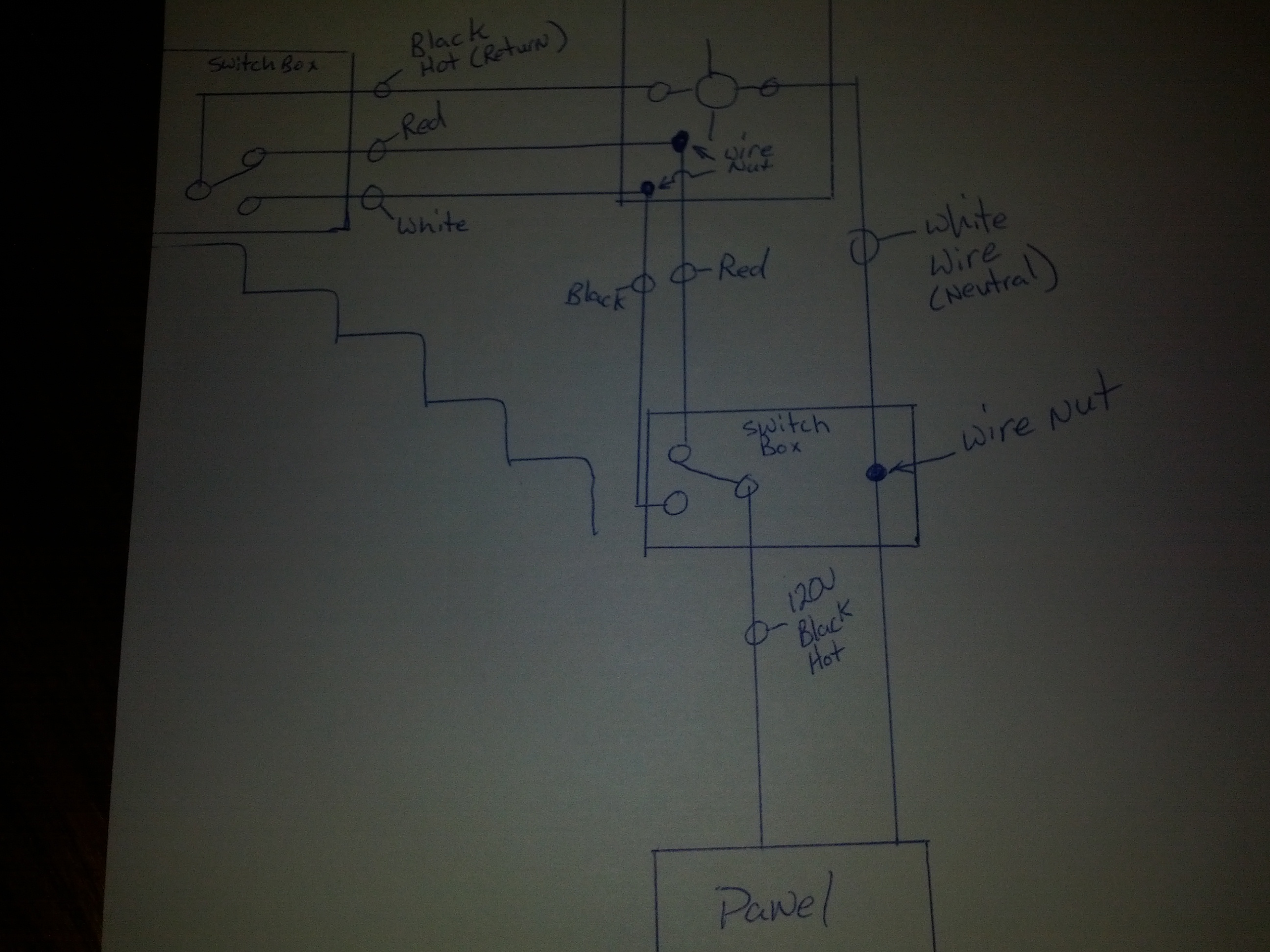
Hand-Drawn 3-Way Switch Wiring Diagram - 120V Light Circuit with Two Switch Boxes
Reference · 1975-1979 F-150All 10 wiring diagrams
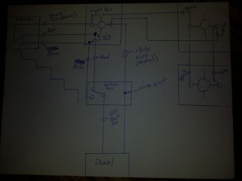
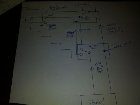
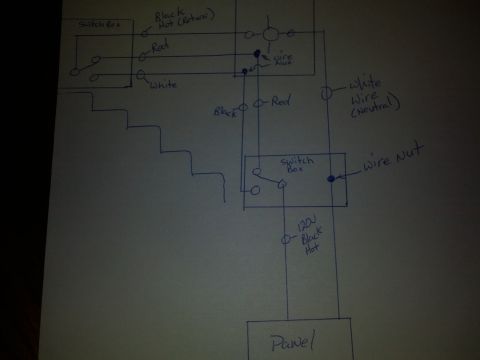
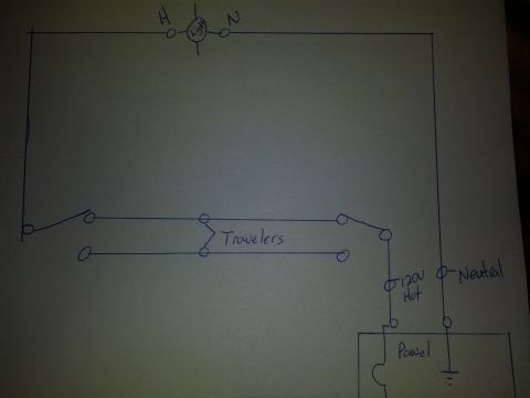

Hand-drawn electrical wiring diagram showing switch boxes, wire nuts and color-coded black, red and white conductors to a panel.
Part of 1975-1979 Ford F-150 Wiring Diagrams
This document is a hand-drawn wiring diagram (pen on paper) depicting a 3-way switch lighting circuit, apparently for a stairway light. It shows two switch boxes, each containing a 3-way switch, a light fixture in a ceiling box, and a power source labeled 'Panel' supplying 120V. Conductors are labeled by color and function: a 'Black Hot' feed from the panel (marked '120V Black Hot'), a 'White Wire (Neutral)', 'Red' and 'Black' traveler wires between the switches, a 'Black Hot (Return)' wire carrying switched power to the light, and a 'White' conductor. Wire nut splice points are called out with arrows in both the fixture box and the second switch box. A stair-step sketch on the left suggests the two switches control a light over a staircase from top and bottom. Despite being filed in an automotive gallery for a 1979 Ford F-150, this diagram documents household/shop 120V AC wiring, not vehicle wiring. A reader can learn the basic routing of hot, neutral, and traveler conductors in a two-location (3-way) switch circuit, including where splices (wire nuts) are made.
Is this accurate? Sign in to help verify it.
Frequently asked questions
- What does this diagram show?
- A hand-drawn 120V lighting circuit with two switch boxes (3-way switches), a light fixture, wire nut splice points, and a feed from a panel labeled '120V Black Hot'.
- What wire colors and functions are labeled?
- Black Hot (Return), Red, and White between the first switch box and the light; Black and Red travelers to the second switch box; a White Wire (Neutral); and a 120V Black Hot feed from the Panel.
- Where does power originate in this diagram?
- From the box labeled 'Panel' at the bottom, via a conductor labeled '120V Black Hot', with the White Wire (Neutral) returning to the panel.
- Where are the wire nut splices located?
- Two wire nut splices are shown in the light fixture/ceiling box area, and one wire nut is shown in the second (lower) switch box joining the neutral run.
- Is this a vehicle wiring diagram?
- No. The diagram shows 120V household-style wiring with switch boxes, a light fixture, and a service panel, not automotive wiring.

No comments yet.