Home/
Registry/
Ford/
F-150/
1975-1979/
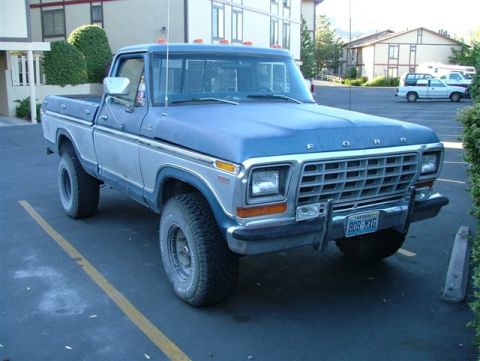
1979 Ford F-150/
Photo
supermotors.net/registry/media/1129824
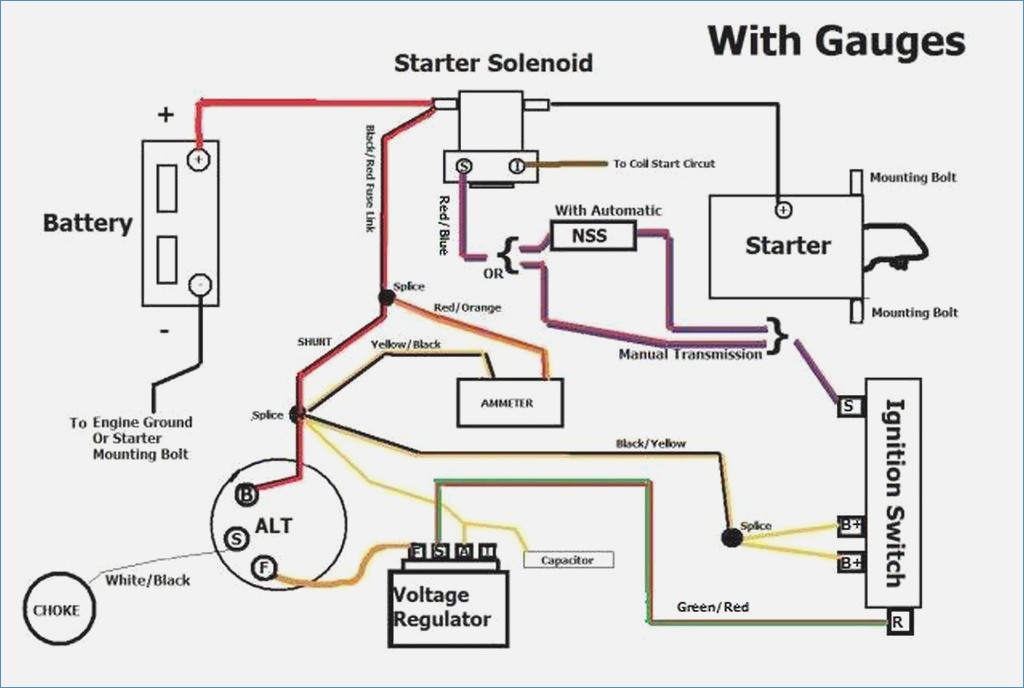
Ford F-150 Charging & Starting Wiring Diagram (With Gauges) - Ammeter, Alternator
Reference · 1975-1979 F-150All 10 wiring diagrams
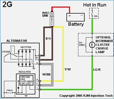
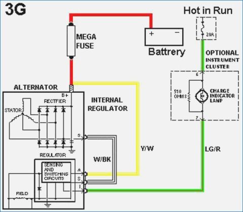
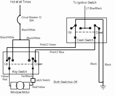
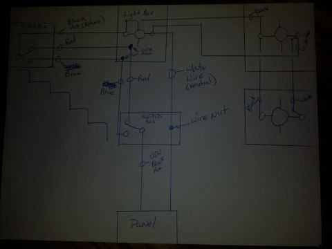
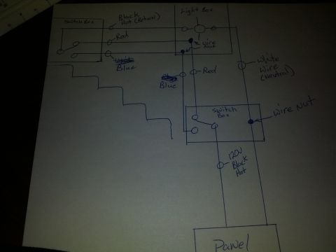
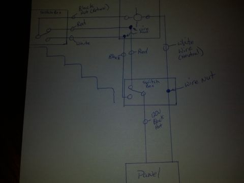
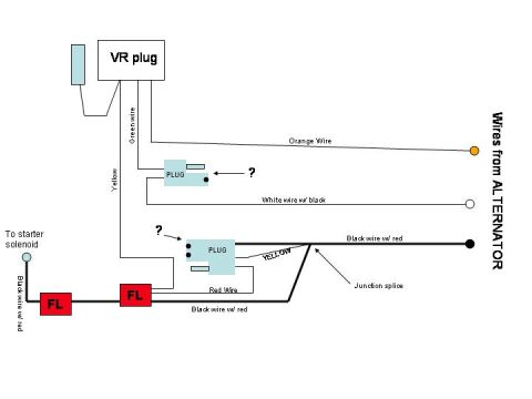


wiring diagram of a charging and starting system with color-coded wires linking battery, alternator, starter solenoid, voltage regulator and ignition switch.
Part of 1975-1979 Ford F-150 Wiring Diagrams
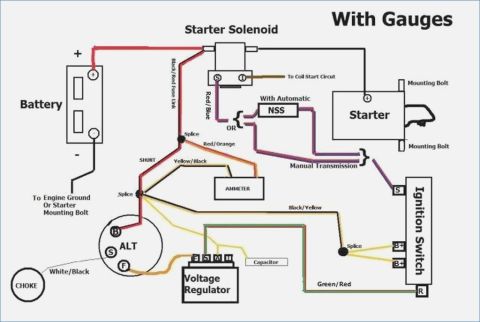
This document is a hand-drawn style wiring diagram titled "With Gauges," showing the charging and starting circuit for a Ford truck equipped with gauges (ammeter) rather than warning lights. It illustrates the battery (with negative lead going to engine ground or starter mounting bolt), the starter solenoid with its S and I terminals (the I terminal feeding the coil start circuit via a Red/Blue wire), and the starter motor with its mounting bolts. A Black/Red fuse link runs from the solenoid to a splice, which feeds the alternator B terminal (Red/Orange with a SHUNT and Yellow/Black wire through the AMMETER), and the ignition switch B+ terminals via Black/Yellow wiring. The alternator (ALT) has B, S, and F terminals, with the F terminal connected to the voltage regulator (terminals F, S, A, I) and a capacitor. A White/Black wire runs to the choke. The diagram distinguishes routing for automatic transmissions (through the NSS, neutral safety switch) versus manual transmissions, both connecting to the ignition switch S terminal. A Green/Red wire connects the voltage regulator circuit to the ignition switch R terminal. Wire colors labeled include Black/Red fuse link, Red/Blue, Red/Orange, Yellow/Black, Black/Yellow, White/Black, and Green/Red.
Is this accurate? Sign in to help verify it.
Frequently asked questions
- What wire color goes from the starter solenoid I terminal to the coil start circuit?
- A Red/Blue wire runs from the solenoid's I terminal to the coil start circuit.
- How does the starting circuit differ between automatic and manual transmissions in this diagram?
- With an automatic transmission the circuit routes through the NSS (neutral safety switch); with a manual transmission it bypasses the NSS. Both paths lead to the ignition switch S terminal.
- What wires connect to the ammeter in this diagram?
- A Red/Orange wire (with a SHUNT) and a Yellow/Black wire connect to the ammeter from a splice off the Black/Red fuse link.
- What terminals are shown on the voltage regulator?
- The voltage regulator has four terminals labeled F, S, A, and I, with a capacitor connected nearby.
- Where does the battery negative cable go?
- The battery negative goes to engine ground or the starter mounting bolt.


No comments yet.