Home/
Registry/
Ford/
F-150/
1975-1979/
1979 Ford F-150/
Photo
supermotors.net/registry/media/1129825
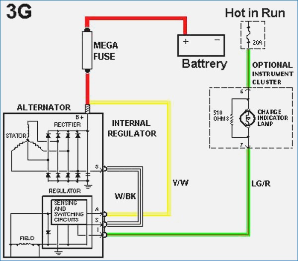
Ford 3G Alternator Wiring Diagram - Mega Fuse, Regulator & Charge Lamp Circuit
Reference · 1975-1979 F-150All 10 wiring diagrams
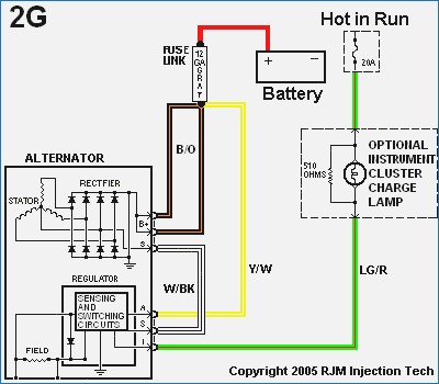
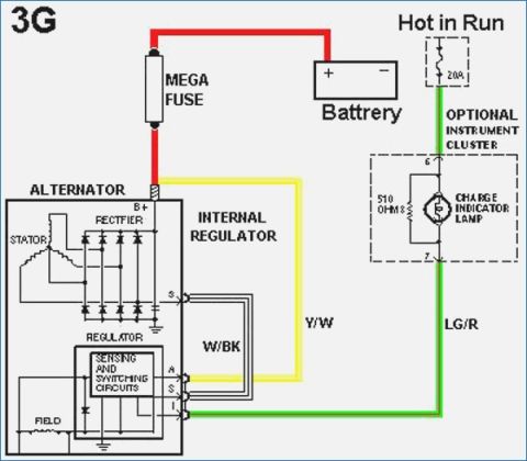
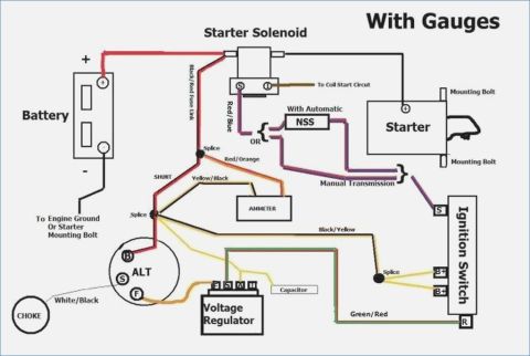
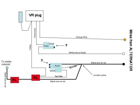




color-coded wiring diagram of a Ford 3G alternator charging circuit with mega fuse, internal regulator and instrument-cluster charge lamp.
Part of 1975-1979 Ford F-150 Wiring Diagrams
This document is a wiring diagram for the Ford 3G alternator charging system. It shows the alternator with its internal components: the stator, rectifier (spelled 'RECTFIER'), and internal regulator containing sensing and switching circuits, plus the field winding. The alternator's B+ output terminal connects through a MEGA FUSE to the battery (spelled 'Battrery'). Three regulator connector terminals are shown: S (stator tap, connected internally with a White/Black 'W/BK' wire), A (battery sense, connected via a Yellow/White 'Y/W' wire to the B+/battery feed downstream of the mega fuse), and I (indicator, connected via a Light Green/Red 'LG/R' wire to the charge indicator lamp). The optional instrument cluster contains the charge indicator lamp with a 510-ohm resistor wired in parallel, connected at cluster pins 6 and 7. Pin 6 is fed from a 'Hot in Run' circuit through a 20A fuse. A reader can learn the basic circuit topology of the 3G alternator: which wire colors serve the sense, indicator, and stator functions, that a mega fuse protects the charge output cable, and that the charge indicator lamp circuit requires either the bulb or the 510-ohm resistor to excite the regulator. No specific vehicle year, model, or part numbers appear on the diagram.
Is this accurate? Sign in to help verify it.
Frequently asked questions
- What wire colors are used in the Ford 3G alternator wiring diagram?
- The diagram shows W/BK (White/Black) for the stator S terminal wire, Y/W (Yellow/White) for the A (battery sense) wire, and LG/R (Light Green/Red) for the I (indicator) wire to the charge lamp.
- How does the 3G alternator connect to the battery?
- The alternator B+ output terminal connects to the battery positive through a MEGA FUSE.
- What resistor is used with the charge indicator lamp?
- A 510-ohm resistor is shown wired in parallel with the charge indicator lamp in the optional instrument cluster.
- What fuse feeds the charge indicator lamp circuit?
- A 20A fuse on a 'Hot in Run' circuit feeds the instrument cluster charge indicator lamp at pin 6; pin 7 carries the LG/R wire to the alternator I terminal.
- What terminals are on the 3G alternator regulator connector?
- The diagram shows S, A, and I terminals on the internal regulator (sensing and switching circuits), plus the B+ output stud.






No comments yet.