Home/
Registry/
Ford/
Bronco/
1992-1996/
1993 Ford Bronco/
Photo
supermotors.net/registry/media/181433
1993 Ford Bronco Fender Flare Install Instructions - Steps 7-9 Photo Guide

Reference · 1992-1996 BroncoAll 143 service procedures
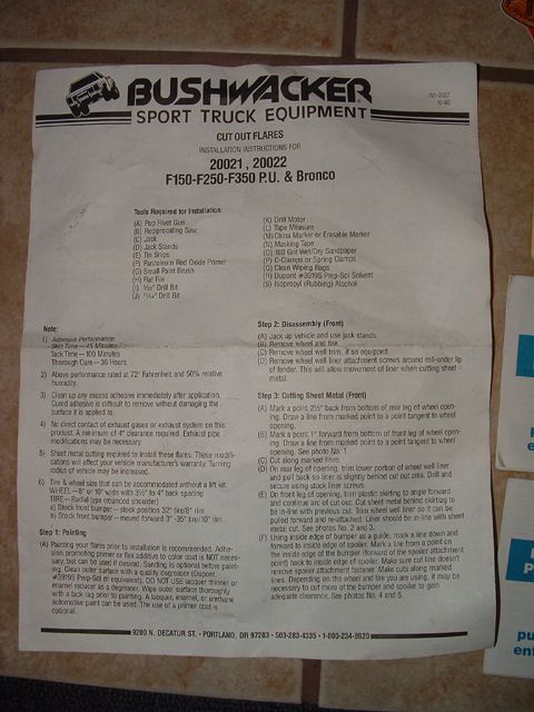
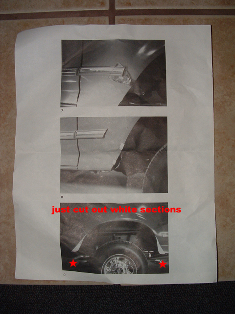
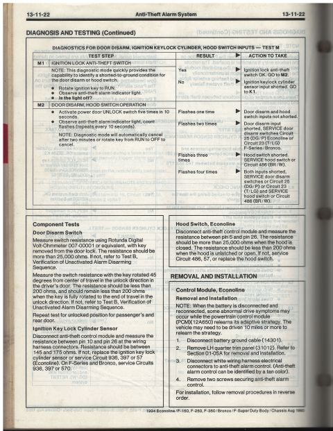
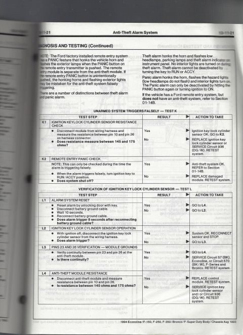
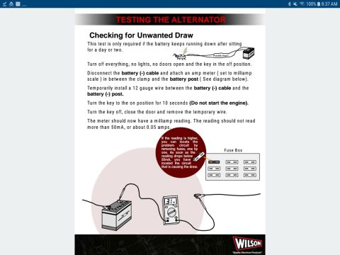
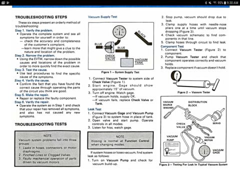


Step-by-step service photos of a vehicle quarter panel with handwritten instruction to cut out marked sections.
Part of 1992-1996 Ford Bronco Service Procedures
This document is a photographed page from an illustrated installation or service instruction sheet, showing three sequentially numbered grayscale photographs (steps 7, 8, and 9). Photos 7 and 8 depict close-up views of a vehicle's body panel and fender/wheel-arch area, apparently illustrating trim or fender flare fitting steps. Photo 9 shows a rear wheel and fender flare region of a truck or SUV, with two red star markers digitally added to highlight specific points on either side of the wheel opening. A red digital annotation reading "just cut out white sections" has been overlaid on the image by the uploader, apparently instructing that white-marked areas visible in the photos should be trimmed away during installation. The page contains no legible printed captions, part numbers, torque values, or model/year identification, so its exact application cannot be confirmed from the document itself. Based on the uploader's attribution, it likely relates to a body trim or fender flare installation procedure for a 1993 Ford Bronco, but nothing visible contradicts or confirms that claim. A reader can learn the general visual sequence of steps 7-9 and the annotated cut locations, but not detailed written instructions.
Is this accurate? Sign in to help verify it.
Frequently asked questions
- What steps of the installation does this page show?
- The page shows three numbered photographs corresponding to steps 7, 8, and 9 of an illustrated installation procedure.
- What does the red annotation on the page say?
- A digitally added red annotation reads 'just cut out white sections,' indicating that white-marked areas shown in the photos should be cut out.
- What do the red stars in photo 9 indicate?
- Two red stars were added to photo 9 on either side of the rear wheel opening, marking specific locations on the fender/flare area referenced by the annotation.
- Does this document list any part numbers or torque specs?
- No. The page contains only photographs and step numbers; no part numbers, torque values, or written specifications are legible.
No comments yet.