Home/
Registry/
Ford/
Bronco/
1992-1996/
1993 Ford Bronco/
Photo
supermotors.net/registry/media/282910
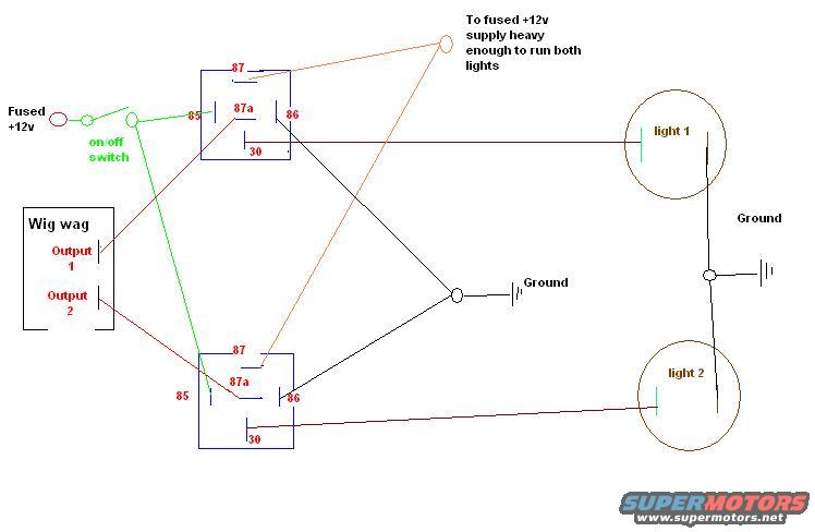
Wig Wag Flasher Wiring Diagram - Dual Relay Setup for Alternating Lights
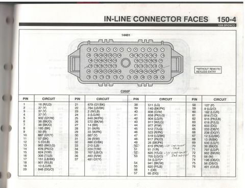
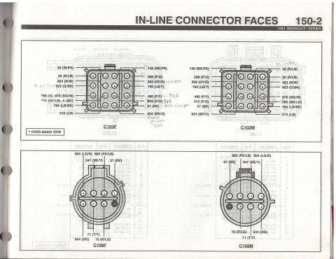
Reference · 1992-1996 BroncoAll 411 wiring diagrams

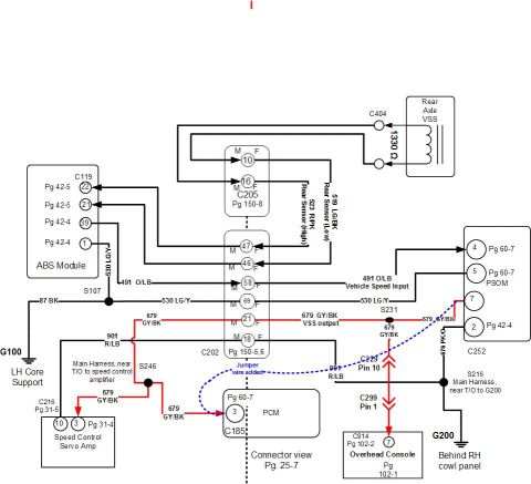
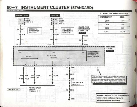
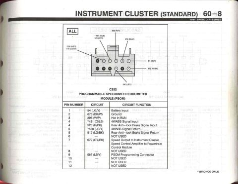
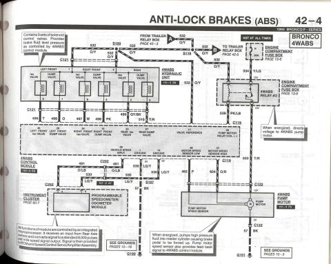
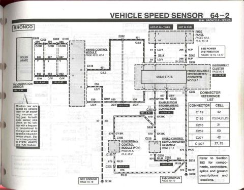
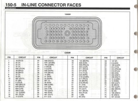
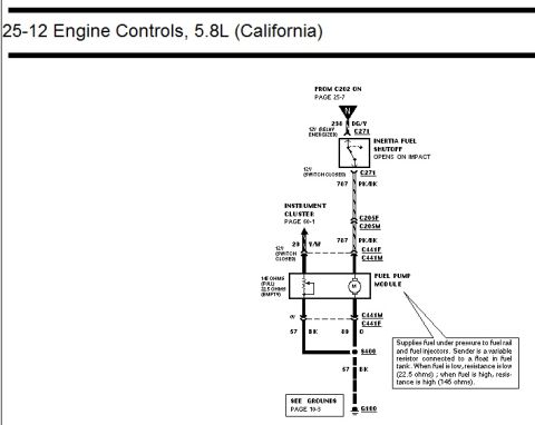
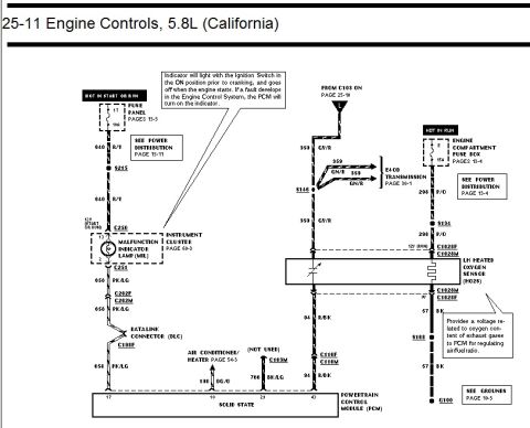








Wiring diagram showing a wig-wag controller and two relays (pins 30/85/86/87/87a) wiring two lights to fused +12V and ground.
Part of 1992-1996 Ford Bronco Wiring Diagrams
This document is a hand-drawn wiring diagram (computer-drawn schematic) showing how to wire a wig-wag flasher module to two lights using two standard 5-pin automotive relays (terminals 30, 85, 86, 87, and 87a). A fused +12v source passes through an on/off switch and energizes terminal 85 of both relay coils, with terminal 86 of each relay tied to ground. A separate fused +12v supply, described as "heavy enough to run both lights," feeds terminal 87 of the top relay and terminal 87a of the bottom relay. The wig-wag module's Output 1 connects to terminal 87a of the top relay, and Output 2 connects to terminal 87 of the bottom relay. Terminal 30 of each relay feeds one light (light 1 from the top relay, light 2 from the bottom relay), and both lights are grounded. The arrangement lets the switch toggle the lights between normal steady operation (fed by the heavy +12v supply) and alternating wig-wag flashing (fed by the wig-wag module outputs). No vehicle year, make, model, part numbers, wire gauges, or fuse amperages are stated in the diagram itself.
Is this accurate? Sign in to help verify it.
Frequently asked questions
- How do the wig wag module outputs connect to the relays?
- Wig wag Output 1 connects to terminal 87a of the top relay, and Output 2 connects to terminal 87 of the bottom relay.
- Which relay terminal feeds each light?
- Terminal 30 of the top relay connects to light 1, and terminal 30 of the bottom relay connects to light 2.
- What does the on/off switch control in this diagram?
- The on/off switch takes fused +12v and feeds terminal 85 of both relay coils, energizing the relays; terminal 86 of each relay goes to ground.
- Where does the steady power for the lights come from?
- From a fused +12v supply 'heavy enough to run both lights,' which feeds terminal 87 of the top relay and terminal 87a of the bottom relay.
- How are the lights grounded?
- Both light 1 and light 2 are shown connected to ground, and the relay coils (terminal 86) also go to ground.






No comments yet.