Home/
Registry/
Ford/
Bronco/
1992-1996/
1996 Ford Bronco/
Photo
supermotors.net/registry/media/1145709
1994 Ford Bronco/F-150 Anti-Theft Alarm Diagnosis - Tests K & L (13-11-21)

Reference · 1992-1996 BroncoAll 142 service procedures
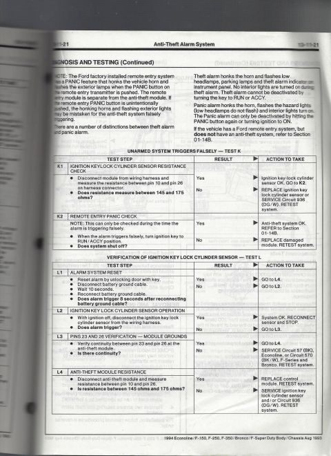
Anti-theft alarm system diagnosis and testing page (1994 Ford): distinguishes theft alarm vs remote panic behavior and gives pinpoint tests, including ignition key-lock cylinder sensor resistance 145-175 ohms.
Part of 1992-1996 Ford Bronco Service Procedures
This page is from the 1994 Ford Econoline/F-150/F-250/F-350/Bronco/F-Super Duty Body/Chassis service manual (dated Aug 1993), Section 13-11 page 21, covering diagnosis and testing of the Anti-Theft Alarm System. It explains how to distinguish the factory remote entry PANIC alarm from the theft alarm: the theft alarm honks the horn, flashes low headlamps, parking lamps and the theft alarm indicator (no interior lights) and cannot be deactivated with the key in RUN or ACCY, while the panic alarm honks the horn, flashes hazard lights and interior lights and is deactivated with the PANIC button or ignition ON. Two pinpoint test tables are provided. Test K (Unarmed System Triggers Falsely) includes an ignition keylock cylinder sensor resistance check between pin 10 and pin 26 (145-175 ohms) and a remote entry panic check, with actions such as servicing Circuit 936 (DG/W) or replacing the module. Test L (Verification of Ignition Key Lock Cylinder Sensor) walks through alarm system reset, sensor operation, ground continuity between pins 23 and 26 (servicing Circuit 57 BK for Econoline or Circuit 570 BK/W for F-Series and Bronco), and anti-theft module resistance, directing replacement of the control module or servicing of the key lock cylinder sensor and Circuit 936 as needed.
Is this accurate? Sign in to help verify it.
Frequently asked questions
- What resistance should the ignition key lock cylinder sensor measure on a 1994 Ford Bronco/F-Series anti-theft system?
- Between 145 and 175 ohms, measured between pin 10 and pin 26 on the harness connector with the module disconnected. If out of range, replace the ignition key lock cylinder sensor or service Circuit 936 (DG/W).
- How can I tell the difference between the theft alarm and the panic alarm?
- The theft alarm honks the horn and flashes the low headlamps, parking lamps and theft alarm indicator on the instrument panel, with no interior lights, and cannot be deactivated by turning the key to RUN or ACCY. The panic alarm honks the horn, flashes the hazard lights (low headlamps do not flash) and turns interior lights on, and can only be deactivated by hitting the PANIC button again or turning the ignition to ON.
- What circuit is serviced if there is no continuity between pins 23 and 26 at the anti-theft module?
- Service Circuit 57 (BK) on Econoline, or Circuit 570 (BK/W) on F-Series and Bronco, then retest the system.
- How do I reset the alarm system for Test L?
- Reset the alarm by unlocking the door with the key, disconnect the battery ground cable, wait 10 seconds, then reconnect the battery ground cable and check whether the alarm triggers 8 seconds after reconnection.
- What should I do if the anti-theft module resistance between pins 10 and 26 is within 145-175 ohms but the alarm still triggers falsely?
- Per Test L4, if resistance is between 145 and 175 ohms, replace the control module and retest the system.






No comments yet.