Nissan Micra Manual Transmission Reassembly Steps 8-13 - Service Manual MT-24
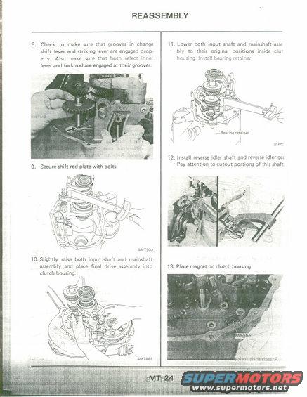
Service manual page MT-24 continuing transaxle reassembly with illustrations for final drive, bearing retainer and magnet.
This is page MT-24 from a factory service manual's Manual Transmission (MT) section, covering steps 8 through 13 of the transaxle reassembly procedure. Step 8 instructs the technician to verify that the grooves in the change shift lever and striking lever are properly engaged, and that the select inner lever and fork rod engage at their grooves. Step 9 covers securing the shift rod plate with bolts (illustration SMT932). Step 10 directs slightly raising the input shaft and mainshaft assembly and placing the final drive assembly into the clutch housing (illustration SMT885). Step 11 covers lowering the input shaft and mainshaft assembly to their original positions inside the clutch housing and installing the bearing retainer. Step 12 covers installing the reverse idler shaft and reverse idler gear, with a caution to pay attention to the cutout portions of the shaft. Step 13 instructs placing the magnet on the clutch housing. The page includes two photographs and three exploded-line illustrations showing hand and tool positions during assembly. No torque values, part numbers, or model/year applicability appear on this page; it is one page of a larger multi-page manual scan set uploaded for a 1990 Nissan Micra.
Is this accurate? Sign in to help verify it.
Frequently asked questions
- What should be checked when engaging the change shift lever during reassembly?
- Check that the grooves in the change shift lever and striking lever are engaged properly, and also make sure both the select inner lever and fork rod are engaged at their grooves (step 8).
- When is the final drive assembly installed into the clutch housing?
- In step 10: slightly raise both the input shaft and mainshaft assembly, then place the final drive assembly into the clutch housing.
- What is installed after lowering the input shaft and mainshaft assembly into the clutch housing?
- The bearing retainer is installed after both the input shaft and mainshaft assembly are lowered to their original positions inside the clutch housing (step 11).
- What caution applies when installing the reverse idler shaft?
- Pay attention to the cutout portions of the reverse idler shaft when installing it along with the reverse idler gear (step 12).
- Where does the magnet go during transmission reassembly?
- Step 13 instructs placing the magnet on the clutch housing, as shown in the accompanying photo with the 'Magnet' callout.
Comments
More from this build











No comments yet.