Nissan Micra Manual Transmission MT-19: Final Drive & Shift Control Inspection
Service manual page MT-19 covering final drive assembly and transmission shift control mechanism inspection with figures.
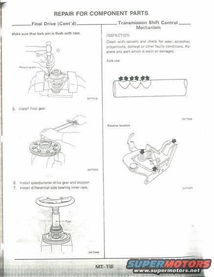
This page, MT-19, from a manual transmission (MT) service manual section titled 'Repair for Component Parts,' covers two topics. The left column continues the Final Drive assembly procedure: it instructs the technician to make sure the lock pin (retaining pin) is flush with the differential case after installation (illustrated by figure SMT916), then to install the final gear (figure SMT620), install the speedometer drive gear and stopper (step 6), and install the differential side bearing inner race using a special tool (step 7, figure SMT648). The right column begins the Transmission Shift Control Mechanism section with an INSPECTION procedure: clean parts with solvent and check for wear, scratches, projections, damage or other faulty conditions, replacing any worn or damaged part. Illustrations highlight inspection points on the fork rod (figure SMT909, showing the detent notches) and the reverse bracket (figure SMT925). A reader learns the assembly sequence for the final drive/differential and which shift control components require visual inspection during a transaxle overhaul. The document itself does not state a year, model, or engine, but its figure numbering (SMT-prefix) and layout are typical of Nissan factory service manuals.
Is this accurate? Sign in to help verify it.
Frequently asked questions
- How should the differential lock pin be checked after installation?
- Make sure the lock pin (retaining pin) is flush with the differential case.
- What is the assembly order after installing the final gear?
- After installing the final gear (step 5), install the speedometer drive gear and stopper (step 6), then install the differential side bearing inner race (step 7).
- How do you inspect the transmission shift control mechanism parts?
- Clean the parts with solvent and check for wear, scratches, projections, damage or other faulty conditions. Replace any part that is worn or damaged.
- Which shift control components are shown with inspection points?
- The fork rod (figure SMT909) and the reverse bracket (figure SMT925) are illustrated with arrows marking inspection points.
Comments
More from this build











No comments yet.