Nissan Micra Automatic Transaxle Governor Shaft & Inhibitor Switch Adjustment AT-10
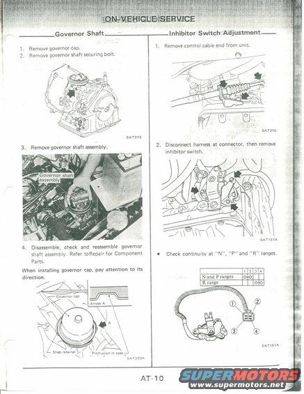
AT-10 on-vehicle service for automatic transaxle governor shaft removal and inhibitor switch adjustment; check continuity at N, P and R ranges.
This is page AT-10 from a Nissan factory service manual's Automatic Transaxle (AT) section, covering "On-Vehicle Service" procedures. The left column details governor shaft removal: remove the governor cap, remove the governor shaft securing bolt, remove the governor shaft assembly, then disassemble, check and reassemble the assembly (referring to the Repair for Component Parts section). A note warns that when installing the governor cap, attention must be paid to its direction, illustrated with callouts for the governor cap, snap retainer, protrusion in case, and "Arrow A" alignment. The right column covers inhibitor switch adjustment: remove the control cable end from the unit, then disconnect the harness at the connector and remove the inhibitor switch. A continuity check table shows that in "N" and "P" ranges continuity exists between connector terminals 1 and 2, and in "R" range between terminals 3 and 4, with an illustration of the switch and its 4-pin connector showing terminal numbering. Illustration reference codes on the page are SAT373, SAT203A, SAT375, SAT197A, and SAT151A. A reader can learn the removal sequence for the governor shaft, the correct orientation caution for the governor cap, and how to test the inhibitor (neutral safety) switch for proper continuity.
Is this accurate? Sign in to help verify it.
Frequently asked questions
- How do you remove the governor shaft on the Nissan automatic transaxle?
- Per this page: 1) Remove the governor cap, 2) Remove the governor shaft securing bolt, 3) Remove the governor shaft assembly, then 4) Disassemble, check and reassemble the governor shaft assembly, referring to the Repair for Component Parts section.
- Is there anything special about installing the governor cap?
- Yes: the manual warns to pay attention to the cap's direction when installing it, showing an illustration with the governor cap, snap retainer, protrusion in case, and an 'Arrow A' alignment reference.
- How do you test the inhibitor switch for continuity?
- Check continuity at the "N", "P" and "R" ranges. In N and P ranges, continuity should exist between connector terminals 1 and 2; in R range, between terminals 3 and 4.
- How is the inhibitor switch removed?
- First remove the control cable end from the unit, then disconnect the harness at the connector and remove the inhibitor switch.
Comments
More from this build











No comments yet.