SuperMotors SuperMotors SUPERMOTORS Search: try “orange Bronco on 35s”
Home/ Registry/ Ford/ Bronco/ 1992-1996/ “The Bronco”/ Photo supermotors.net/registry/media/254784

Ford Bronco Brake Booster Pushrod Adjustment Diagram - Gauge Block Specs

Brake booster pushrod adjustment gauge block dimensioned drawing
Brake booster pushrod adjustment gauge block dimensioned drawingOriginal file
Brake booster pushrod adjustment gauge block dimensioned drawing

Reference · 1992-1996 BroncoAll 142 service procedures
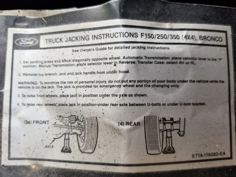
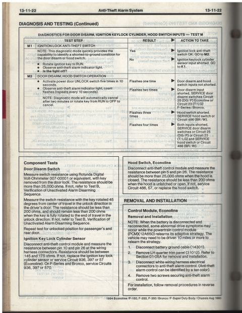
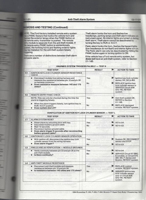
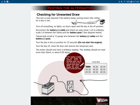
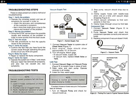
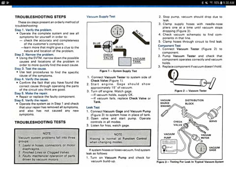
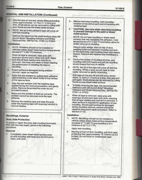
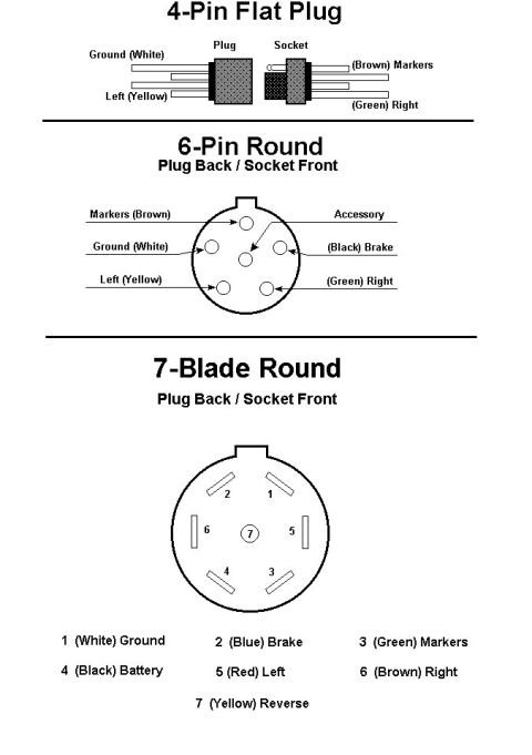
Ford RABS Rear Antilock Brake System Troubleshooting Chart (1992 Bronco) Ring Gear Tooth Contact Pattern Interpretation Chart - Pinion Shim & Backlash Ford Bronco Windshield Wiper Motor Testing & Diagnosis - WCM, C151/C152 Pinouts Ford Bronco Brake Booster Pushrod Adjustment Diagram - Gauge Block Specs Ford EEC-IV Output State Check & Cylinder Balance Test - Code Reader Procedure Ford F150/F250/F350 4x4 & Bronco Truck Jacking Instructions Label E7TA-17A083-EA 1994 Ford Bronco/F-150/Econoline Anti-Theft Alarm Diagnosis Test M (13-11-22) 1994 Ford Bronco/F-150 Anti-Theft Alarm Diagnosis - Tests K & L (13-11-21) Parasitic Battery Draw Test Procedure - Checking for Unwanted Draw (Wilson) Ford Vacuum System Troubleshooting Steps & Tests - Supply, Leak, Component (EVTM) 1996 Ford Bronco Vacuum System Troubleshooting - Supply, Leak & Component Tests 1996 Ford Bronco/F-150 Exterior Trim & Body Side Moulding Removal - Pg 01-08-8 142service procedures1992-1996 Ford Bronco More reference Trailer Connector Wiring Diagram - 4-Pin Flat, 6-Pin Round & 7-Blade PinoutsWiring diagram Ford Bronco PCV Valve & Crankcase Ventilation Tube Exploded DiagramExploded parts Ford truck certification label with 25 numbered callouts explaining GVWR, tire, VIN and code fieldsSpec plate '91-93 Ford truck drive axle application chart for Bronco, F-150, F-250, F-350 and F-Super DutyManual page 1992 Ford Bronco/F-Series 5.0L 5.8L Engine Compartment Connector LocationsSchematic Ford 5.0L V8 Vacuum Hose Routing Diagram - EGR, AIR, FPRC & Carbon CanisterVacuum routing Ford 255/302/351W & 351M/400 V8 Intake Manifold Bolt Tightening SequenceTorque spec Brake Booster to Master Cylinder Adapter Plate Blueprint - Ford Bronco SwapBlueprint 1994-1995 BMW 3 Series Owner's Manual Booklet Set - Warranty, Radio & AccessoriesBrochure Ford Bronco/F-Series Fuse 18 (10A) - Speedometer, Air Bag, Shift ControlFuse chart

Brake booster pushrod adjustment procedure showing gauge block setup with dimensioned measurements and adjustment screw.

Part of 1992-1996 Ford Bronco Service Procedures

AI caption · Photo 97 of 272

This document is a labeled technical diagram titled "Brake Booster Pushrod Adjustment," uploaded to a 1992 Ford Bronco gallery. It illustrates the use of a gauge block placed against the face of the brake vacuum booster to check and set the length of the booster pushrod via its adjustment screw. The diagram shows a cross-section of the booster mounting studs, the pushrod extending through the gauge block cutout, and the adjustment screw tip contacting the gauge. Key dimensions are called out: the gauge block overall height of 74.61 mm (2-15/16 inch), a 19.05 mm (3/4 inch) dimension for the center cutout, and the critical pushrod protrusion specification of 24.89-25.27 mm (0.980-0.995 inch), with the 0.995 inch depth shown as the gauge step. The figure carries the Ford illustration reference H1330-J. A reader can learn the correct gauge block dimensions to fabricate or verify one, and the proper pushrod length range so that the adjustment screw is set correctly, avoiding brake drag (pushrod too long) or excessive pedal travel (pushrod too short). The document itself gives no year, model, or engine applicability, so it does not contradict the claimed 1992 Ford Bronco.

Is this accurate? Sign in to help verify it.

Frequently asked questions

What is the correct brake booster pushrod adjustment specification?
The diagram specifies a pushrod dimension of 24.89-25.27 mm (0.980-0.995 inch), measured with a gauge block against the booster.
How is the booster pushrod adjusted?
Via an adjustment screw on the end of the pushrod, checked with a gauge block placed over the booster mounting studs.
What are the gauge block dimensions shown in the diagram?
The gauge block is 74.61 mm (2-15/16 inch) overall with a 19.05 mm (3/4 inch) center cutout and a 0.995 inch step depth.
What is the illustration reference number on this diagram?
The figure is marked H1330-J.

Comments

No comments yet.

More 1992-1996 Broncos