Ring Gear Tooth Contact Pattern Interpretation Chart - Pinion Shim & Backlash

Reference · 1992-1996 BroncoAll 142 service procedures
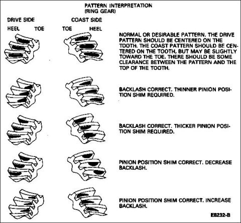


Ring gear tooth contact pattern interpretation chart pairing drive/coast patterns with backlash and pinion shim corrections.
Part of 1992-1996 Ford Bronco Service Procedures
This document is a ring gear tooth contact pattern interpretation chart used when setting up a differential (ring and pinion gears). It shows five pairs of illustrated gear teeth, each pair depicting the contact pattern on the drive side (heel and toe labeled) and coast side (toe and heel labeled) of the ring gear teeth. Each illustration pair is accompanied by an interpretation and corrective action: (1) the normal or desirable pattern, where the drive pattern is centered on the tooth and the coast pattern is centered but may be slightly toward the toe, with clearance between the pattern and the top of the tooth; (2) backlash correct but a thinner pinion position shim is required; (3) backlash correct but a thicker pinion position shim is required; (4) pinion position shim correct but backlash should be decreased; and (5) pinion position shim correct but backlash should be increased. The figure is referenced as E6232-B. A technician can use this chart after painting the ring gear with marking compound and rotating the gears to compare the resulting contact pattern to these examples and determine whether to change the pinion shim thickness or adjust backlash.
Is this accurate? Sign in to help verify it.
Frequently asked questions
- What does a normal or desirable ring gear contact pattern look like?
- The drive pattern should be centered on the tooth, and the coast pattern should be centered on the tooth but may be slightly toward the toe. There should be some clearance between the pattern and the top of the tooth.
- What should I do if backlash is correct but the pattern is wrong?
- Depending on the pattern shown, either a thinner pinion position shim or a thicker pinion position shim is required.
- What should I do if the pinion position shim is correct but the pattern is off?
- Adjust the backlash: either decrease backlash or increase backlash depending on which pattern the chart matches.
- Which sides of the gear teeth are shown in the pattern chart?
- Both the drive side and the coast side of the ring gear teeth are shown, with heel and toe positions labeled for each.

No comments yet.