Ford Steering Column Exploded Parts Diagram (Tilt Column, Air Bag & Non-Air Bag)

Reference · 1992-1996 BroncoAll 169 exploded parts diagrams
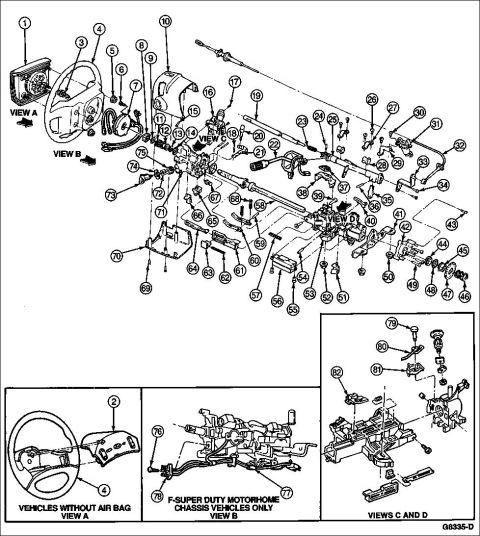
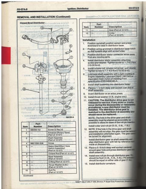
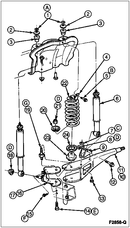
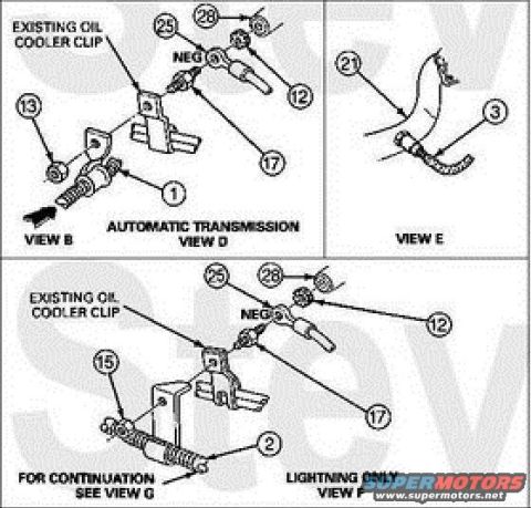
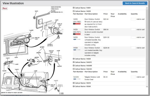
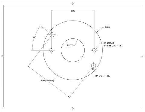

Exploded parts diagram of a steering column and wheel assembly with numbered components and multiple views.
Part of 1992-1996 Ford Bronco Exploded Parts Diagrams
This document is a factory-style exploded parts diagram of a Ford steering column assembly, showing the complete disassembled column with numbered callouts from 1 through 82. The main illustration depicts the steering wheel, air bag module area (View A), upper and lower column shrouds, multifunction/turn signal switch area, ignition lock cylinder and actuator, steering shaft, tilt mechanism components, bearings, snap rings, and the lower column mounting brackets and intermediate shaft components. Three supplemental inset views appear along the bottom: View A shows the steering wheel arrangement for 'Vehicles Without Air Bag' (callouts 2 and 4); View B shows a column variant labeled 'F-Super Duty Motorhome Chassis Vehicles Only' (callouts 76, 77, 78); and 'Views C and D' show detail of the ignition lock/actuator housing assembly (callouts 79, 80, 81, 82). The drawing carries the Ford illustration reference number G8335-D. No parts legend, part numbers, torque specifications, or year applicability table is included on this page, the corresponding key identifying each numbered item presumably appears on a companion page. A reader can use this diagram to understand the physical arrangement and disassembly order of the steering column components and to cross-reference the item numbers against a parts legend.
Is this accurate? Sign in to help verify it.
Frequently asked questions
- What does this diagram show?
- An exploded view of a Ford steering column assembly with numbered callouts 1 through 82, including the steering wheel, column shrouds, ignition lock area, steering shaft, and mounting components, plus detail Views A, B, C, and D.
- Does the diagram cover columns without an air bag?
- Yes. A bottom inset labeled 'Vehicles Without Air Bag: View A' shows the steering wheel arrangement (callouts 2 and 4) for non-air-bag vehicles.
- Is there a special version for F-Super Duty motorhome chassis?
- Yes. View B at the bottom is labeled 'F-Super Duty Motorhome Chassis Vehicles Only' and shows that column variant with callouts 76, 77, and 78.
- Does this page include a parts list identifying each numbered item?
- No. Only the numbered callouts and view captions appear; no legend, part numbers, or descriptions are on this page.
- What is the drawing reference number?
- The illustration is marked G8335-D in the lower right corner.


No comments yet.