1992 Ford Bronco Overhead Console Exploded Parts Diagram - Assembly View

Reference · 1992-1996 BroncoAll 169 exploded parts diagrams


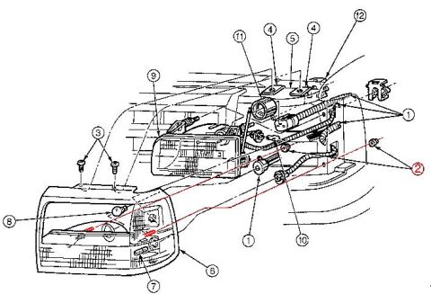







Exploded parts diagram of an overhead console assembly with numbered brackets, housing and lamp components.
Part of 1992-1996 Ford Bronco Exploded Parts Diagrams
This document is an exploded parts diagram of an overhead console assembly, uploaded to a 1992 Ford Bronco gallery. The illustration shows the vehicle's roof structure at the top, with seven numbered callouts identifying components in their disassembled/exploded positions. Item 2 is a mounting bracket or plate that fastens to the roof panel. Item 7 is a wiring harness with multiple connectors that feeds the console. Item 1 is the main overhead console housing itself. Items 5 and 6 appear to be sub-components such as a lamp housing or reading-light module (item 6 shows two circular openings, likely for map light bulbs or lenses). Item 3 is a lower trim panel with a grille or vent pattern, and item 4 is a lens or cover piece. The diagram contains no legend, part numbers, torque specifications, or textual descriptions, it is purely a visual reference showing how the overhead console components stack together and mount to the roof. A reader can learn the relative assembly order and orientation of the console pieces, which would be useful for removal, disassembly, or reassembly of the overhead console, but must consult a separate parts list to identify part names and numbers for the callouts.
Is this accurate? Sign in to help verify it.
Frequently asked questions
- What does this diagram show?
- An exploded view of an overhead console assembly with seven numbered callouts, showing the mounting bracket at the roof, wiring harness, main console housing, and lower trim/lamp components.
- How many components are identified in the overhead console diagram?
- Seven numbered callouts (1 through 7) identify components, from the roof mounting bracket (2) down to the lower trim pieces (3 and 4).
- Does the diagram include part numbers or a parts legend?
- No. The diagram contains only numbered callouts with leader lines; there is no legend, part list, or part numbers visible.
- How does the overhead console mount to the vehicle?
- Based on the diagram, a bracket/plate (callout 2) attaches to the roof structure, and the main console housing (callout 1) mounts beneath it, with a wiring harness (callout 7) routed to the console.






No comments yet.