SuperMotors SuperMotors SUPERMOTORS Search: try “orange Bronco on 35s”
Home/ Registry/ Ford/ Bronco/ 1992-1996/ “The Bronco”/ Photo supermotors.net/registry/media/254879

Ford C-II Power Steering Pump Exploded View Diagram - Parts Breakdown

Exploded view of C-II power steering pump with numbered components
Exploded view of C-II power steering pump with numbered componentsOriginal file
Exploded view of C-II power steering pump with numbered components

Reference · 1992-1996 BroncoAll 169 exploded parts diagrams

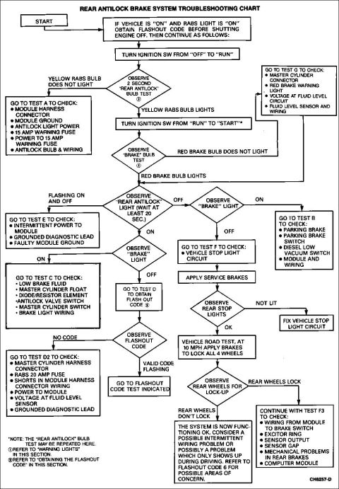
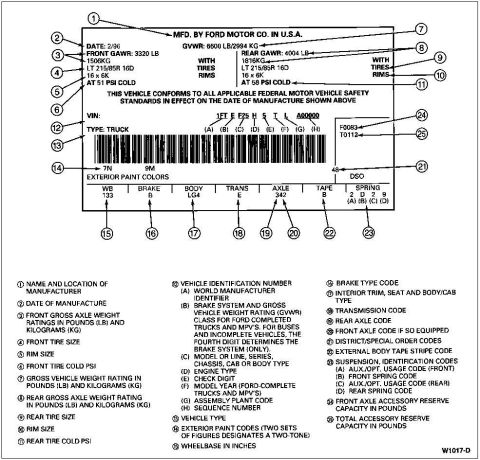
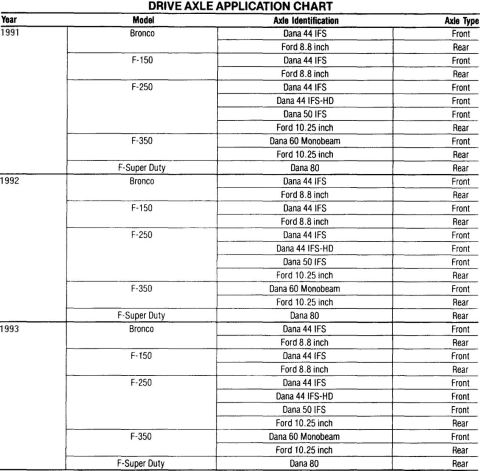
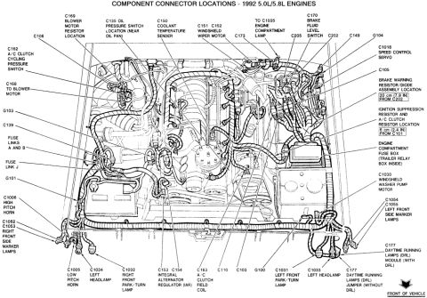
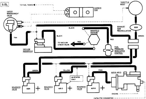
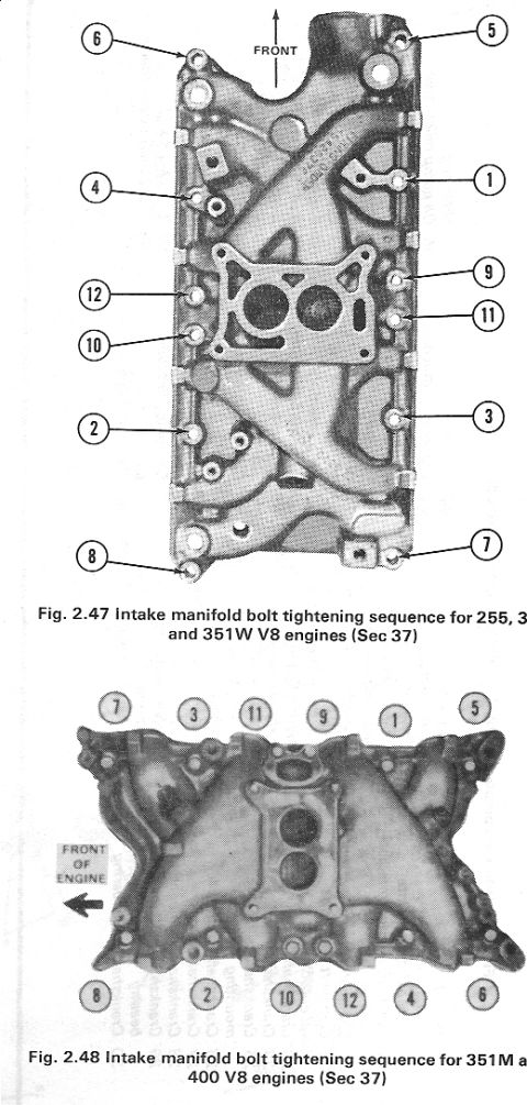
Ford Steering Column Exploded Parts Diagram (Tilt Column, Air Bag & Non-Air Bag) Ford Permanent Magnet Planetary Starter Exploded Diagram - 1992 Bronco 1978-79 Ford Bronco Lower Body Sheet Metal Exploded Parts Diagram Ford C-II Power Steering Pump Exploded View Diagram - Parts Breakdown 1992 Ford Bronco Overhead Console Exploded Parts Diagram - Assembly View Ford Bronco Overhead Console Exploded Parts Diagram - Roof Console Assembly Ford IAC Valve Cutaway Diagrams - Hitachi, Vented Hitachi & NipponDenso 1978-1979 Ford Bronco Radiator Grille Exploded Parts Diagram & Part Numbers 1996 Ford Bronco/F-150 Distributor Exploded Parts Diagram & Installation 03-07A-6 Ford Bronco Front Coil Spring & Shock Absorber Exploded Diagram (F2858-Q) Ford Bronco/F-Series Engine Block Ground Cable Diagram - Neg Battery Cable Views Ford Bronco Tailgate Window Switch & Wiring Harness Parts Diagram - 14529, 14A353 169exploded parts diagrams1992-1996 Ford Bronco More reference Trailer Connector Wiring Diagram - 4-Pin Flat, 6-Pin Round & 7-Blade PinoutsWiring diagram Ford RABS Rear Antilock Brake System Troubleshooting Chart (1992 Bronco)Service procedure Ford truck certification label with 25 numbered callouts explaining GVWR, tire, VIN and code fieldsSpec plate '91-93 Ford truck drive axle application chart for Bronco, F-150, F-250, F-350 and F-Super DutyManual page 1992 Ford Bronco/F-Series 5.0L 5.8L Engine Compartment Connector LocationsSchematic Ford 5.0L V8 Vacuum Hose Routing Diagram - EGR, AIR, FPRC & Carbon CanisterVacuum routing Ford 255/302/351W & 351M/400 V8 Intake Manifold Bolt Tightening SequenceTorque spec Smittybilt XRC Gen 3 Winch Box - 9.5K/12K Recovery Winch Features & CalloutsBrochure Brake Booster to Master Cylinder Adapter Plate Blueprint - Ford Bronco SwapBlueprint Ford Bronco/F-Series Fuse 18 (10A) - Speedometer, Air Bag, Shift ControlFuse chart

Exploded parts diagram of a C-II power steering pump showing housing, rotor, seals and internal components.

Part of 1992-1996 Ford Bronco Exploded Parts Diagrams

AI caption · Photo 132 of 272

This document is an exploded parts view of a Ford C-II (C2) power steering pump. The line-art diagram shows the pump disassembled along its axis with numbered callouts 1 through 23 identifying individual components, including the pump housing/body casting, O-rings and seals, the drive shaft with splined end, a rotor with vanes, cam ring, pressure plates, the filler cap and dipstick assembly, the outlet fitting with associated spring, valve, and small O-ring components, the reservoir/housing shell, and mounting plates. The caption at the bottom reads 'C-II POWER STEERING PUMP EXPLODED VIEW' with figure reference number G6931-B in the lower right corner. No parts legend, part names, part numbers, torque specifications, or year/model applicability information is printed on this page, only the numbered callouts. A reader can use this diagram to understand the assembly order and relative position of the internal components of the C-II power steering pump when disassembling or rebuilding it, such as the location of seals and O-rings relative to the shaft, rotor, and housing, and how the pressure relief/outlet fitting components stack together.

Is this accurate? Sign in to help verify it.

Frequently asked questions

What does this diagram show?
An exploded view of the Ford C-II power steering pump, with numbered callouts (1-23) identifying the individual components and their assembly order.
Does this diagram include a parts list or part names?
No. The scan contains only numbered callouts on the drawing; no legend, part names, or part numbers are printed on the page.
How many components are called out in the exploded view?
The callouts run from 1 to 23, with some numbers (such as 3 and 16) pointing to multiple items.
What figure reference is on this document?
The figure number in the lower right corner reads G6931-B.

Comments

No comments yet.

More 1992-1996 Broncos