Home/
Registry/
Ford/
LTD Crown Victoria/
1983-1991/
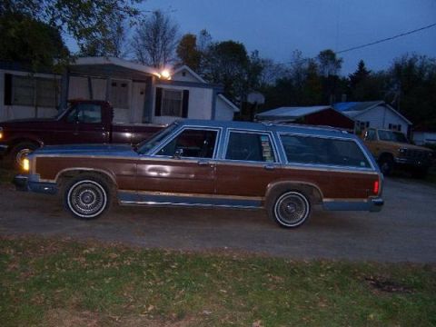
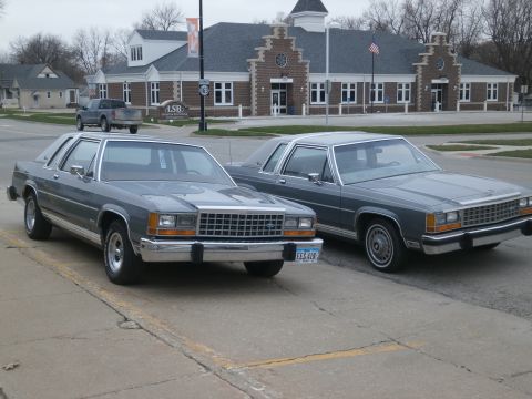
“Grey October”/
Photo
supermotors.net/registry/media/269955
1991 Ford Crown Victoria Instrument Cluster & Dash Illumination Wiring Diagram
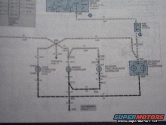
Wiring diagram showing instrument cluster illumination, fuse panel and HVAC selector illumination circuits.
Part of 1983-1991 Ford LTD Crown Victoria Wiring Diagrams
This is a photographed page from a Ford factory-style wiring diagram (Electrical & Vacuum Troubleshooting Manual format) showing the instrument panel illumination circuit. The diagram traces circuit 19 (wire color code LB/R, light blue/red) from the headlamp/light switch area at the top of the page through a fuse in the fuse panel (cross-referenced to "FUSE PANEL PAGE 20") and out to multiple dash illumination loads: the clock illumination, another illumination lamp, the A/C-heater function selector illumination, and the instrument cluster illumination (drawn with two bulb symbols and connector references). Ground return paths are shown as black (57 BK) wires along the bottom, with a cross-reference callout to a grounds page. Connector numbers (C-series) and splice points are marked but mostly too blurry to read reliably. A small legend or connector pinout table appears in the top-left corner but is illegible. The page uses standard Ford EVTM conventions: circled numbers as page cross-references, dashed lines for illumination feed and ground circuits, and blue-shaded blocks for components. A reader could use this page to understand how power flows to the dash lighting and where the illumination circuit grounds, though the photo quality limits reading exact fuse ratings and connector IDs.
Is this accurate? Sign in to help verify it.
Frequently asked questions
- What circuit does this wiring diagram page cover?
- It covers the dash illumination circuit, including the clock illumination, A/C-heater function selector illumination, and instrument cluster illumination, fed through the fuse panel.
- What wire color is used for the illumination feed circuit?
- The feed wiring is labeled circuit 19 with color code LB/R (light blue/red), repeated along multiple wire runs.
- Where does the diagram say the fuse panel details are located?
- A callout points to the fuse panel and references 'FUSE PANEL PAGE 20' for details.
- How is the instrument cluster illumination shown?
- It is drawn as a blue-shaded block labeled 'INSTRUMENT CLUSTER ILLUMINATION' containing two bulb symbols, with C-series connector references at the top and bottom of the block.
- What color are the ground wires in this circuit?
- Ground return wires along the bottom of the diagram are labeled 57 BK (black), with a cross-reference to a grounds page.
Comments
More from this build




No comments yet.