Home/
Registry/
Ford/
LTD Crown Victoria/
1983-1991/
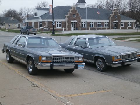
“babycakes”/
Photo
supermotors.net/registry/media/206731
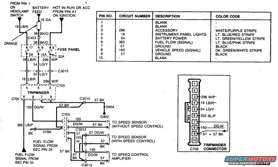
Ford Tripminder Wiring Diagram - C705 Connector Pinout & Wire Colors (K6248-E)
Reference · 1983-1991 LTD Crown VictoriaAll 23 wiring diagrams
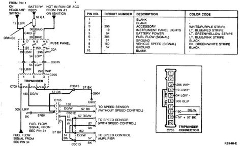
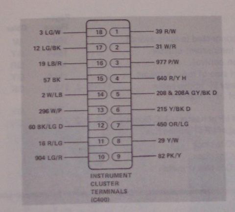
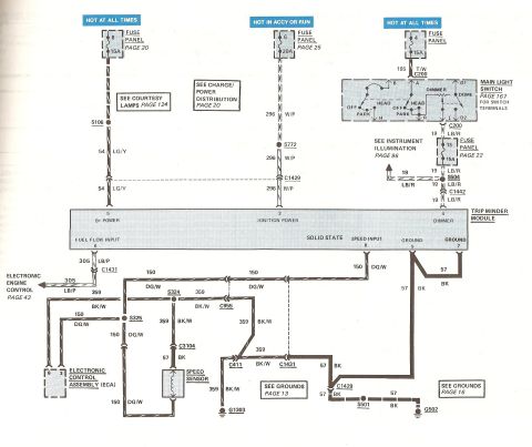

Wiring diagram for the Tripminder with a pin-number, circuit and color-code table plus a labeled connector pinout.
Part of 1983-1991 Ford LTD Crown Victoria Wiring Diagrams
This document is a Ford Tripminder (trip computer) wiring diagram, drawing number K6248-E. It shows the complete circuit for the Tripminder module including its power feeds: a 19 LB/R circuit from pin 1 of the headlamp switch (through a 5A fuse), a battery feed via a 16 GA orange fusible link and circuit 38 BK/O through connector C403 to a 20A fuse (circuit 54 LG/Y), and a hot-in-run-or-accessory feed from ignition pin A1 through a 15A fuse (circuit 296 W/P). The diagram traces grounds (circuit 57 BK) through splice S904 to ground G902, the fuel flow signal (circuit 305 LB/P) from EEC pin 34, and vehicle speed signal (circuit 150 DG/W) routing to the speed sensor (with and without speed control) and speed control amplifier via connectors C705, C3012, C3013, and C3015. A pin table lists all ten pins of the Tripminder connector C705 with circuit numbers, descriptions, and wire color codes, and a connector face diagram shows the physical pinout. This is useful for diagnosing Tripminder power, ground, speed signal, and fuel flow signal issues.
Is this accurate? Sign in to help verify it.
Frequently asked questions
- What are the pin assignments for the Ford Tripminder connector C705?
- Pin 1: blank; Pin 2: blank; Pin 3: circuit 296 accessory (white/purple stripe); Pin 4: circuit 19 instrument panel lights (lt. blue/red stripe); Pin 5: circuit 54 battery power (lt. green/yellow stripe); Pin 6: circuit 305 fuel flow signal (lt. blue/pink stripe); Pin 7: circuit 57 ground (black); Pin 8: circuit 150 vehicle speed signal (dk. green/white stripe); Pin 9: circuit 57 ground (black); Pin 10: blank.
- What fuses power the Tripminder?
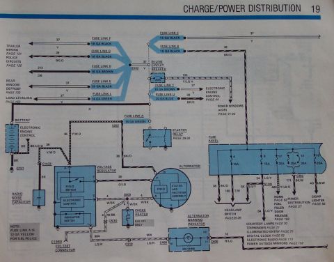
- Three fuse panel positions feed it: a 5A fuse (position 17) on circuit 19 LB/R from the headlamp switch, a 15A fuse (position 8) on circuit 296 W/P hot in run or accessory from ignition pin A1, and a 20A fuse (position 6) on circuit 54 LG/Y battery power fed through a 16 GA orange fusible link and circuit 38 BK/O.
- Where does the Tripminder get its fuel flow signal?
- The fuel flow signal comes from EEC pin 34 on circuit 305 LB/P (lt. blue/pink stripe), entering the Tripminder at connector pin 6.
- How is the vehicle speed signal routed?
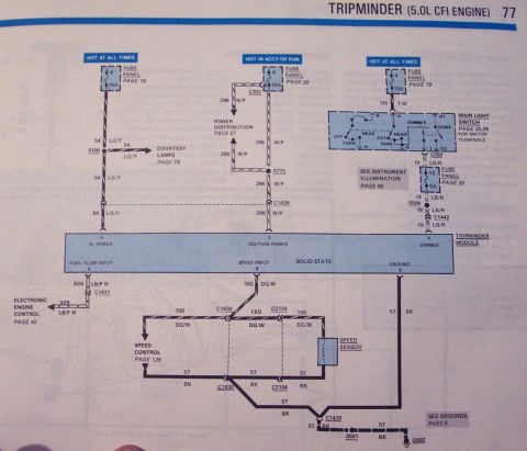
- Circuit 150 DG/W (dk. green/white stripe) at Tripminder pin 8 runs to the speed sensor (without speed control) through C705, to the speed sensor (with speed control) through C3012 on 57 DG/W, and to the speed control amplifier through C3013.
- Where does the Tripminder ground?
- Ground circuit 57 BK passes through connector C3015 and splice S904 to ground point G902; pins 7 and 9 of the connector are grounds (black wires).

No comments yet.