Home/
Registry/
Ford/
LTD Crown Victoria/
1983-1991/
“Grey October”/
Photo
supermotors.net/registry/media/269957
Ford Crown Victoria / Grand Marquis Warning Indicator Wiring Diagram - Cluster

Reference · 1983-1991 LTD Crown VictoriaAll 23 wiring diagrams
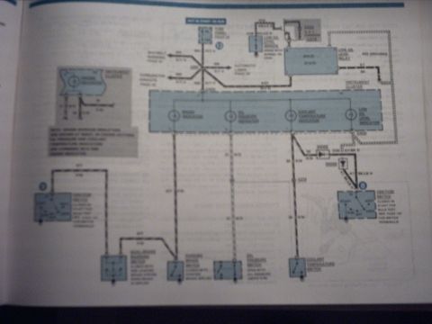
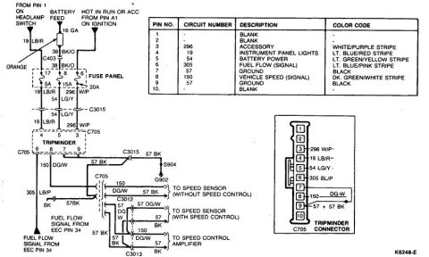
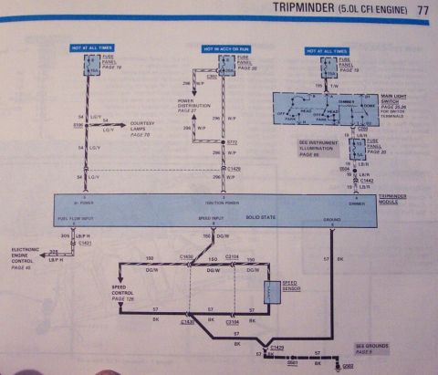
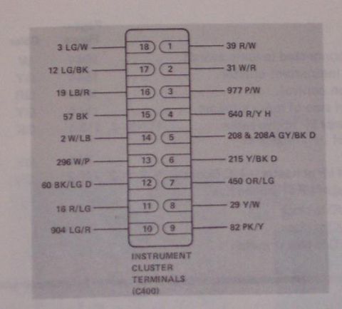

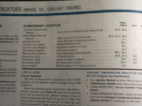
Wiring diagram showing warning indicators, instrument cluster, ignition switch and various sensor and switch circuits.
Part of 1983-1991 Ford LTD Crown Victoria Wiring Diagrams
This is a photographed page from an automotive wiring diagram manual showing the warning indicator circuits for the instrument cluster. The diagram is fed from the fuse panel on a circuit that is hot in START or RUN, splitting at a splice to feed the seatbelt warning, automatic lamps, and the cluster warning lamps. The instrument cluster (shown as a dashed box) contains four indicators: brake indicator, oil pressure indicator, coolant temperature indicator, and low oil level indicator. Supporting components include a low oil level sensor (open with normal oil level), a low oil level relay, two diodes, an ignition switch (closed in START for bulb test, with START/ACC/RUN/OFF/LOCK positions), a dual brake warning switch, parking brake switch, oil pressure switch (open with normal oil pressure), and coolant temperature switch. Ground points (G210) and connectors are indicated, along with wire circuit numbers such as 640 R/Y, 31 R/W, 39 R/W, and 977. A note references Grand Marquis models where oil pressure and coolant temperature indicators are combined. The photo is significantly blurred, so many page references, connector numbers, and wire color details are not fully readable, but the overall circuit layout and component functions can be followed.
Is this accurate? Sign in to help verify it.
Frequently asked questions
- What warning indicators are shown in this instrument cluster wiring diagram?
- Four indicators inside the instrument cluster: brake indicator, oil pressure indicator, coolant temperature indicator, and low oil level indicator.
- When does this circuit receive power?
- The circuit is fed from the fuse panel and is labeled 'HOT IN START OR RUN'.
- How does the low oil level sensor operate?
- The low oil level sensor is open with normal oil level, and works with a low oil level relay to control the low oil level indicator.
- How is the bulb test performed for the warning lamps?
- The ignition switch is closed in START for the bulb test, grounding the indicator circuits when the key is in the START position.
- What switches trigger the brake warning indicator?
- The dual brake warning switch (closed with a brake system fault) and the parking brake switch (closed with the parking brake applied).

No comments yet.