Home/
Registry/
Ford/
LTD Crown Victoria/
1983-1991/
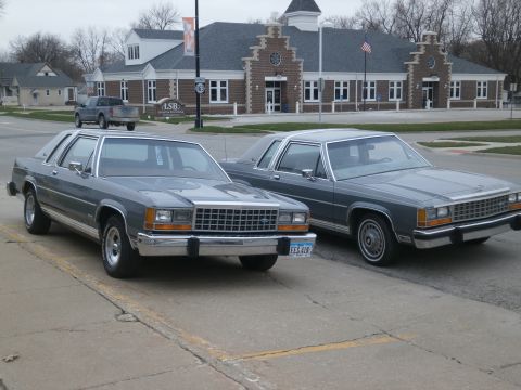
“Bertha”/
Photo
supermotors.net/registry/media/829359
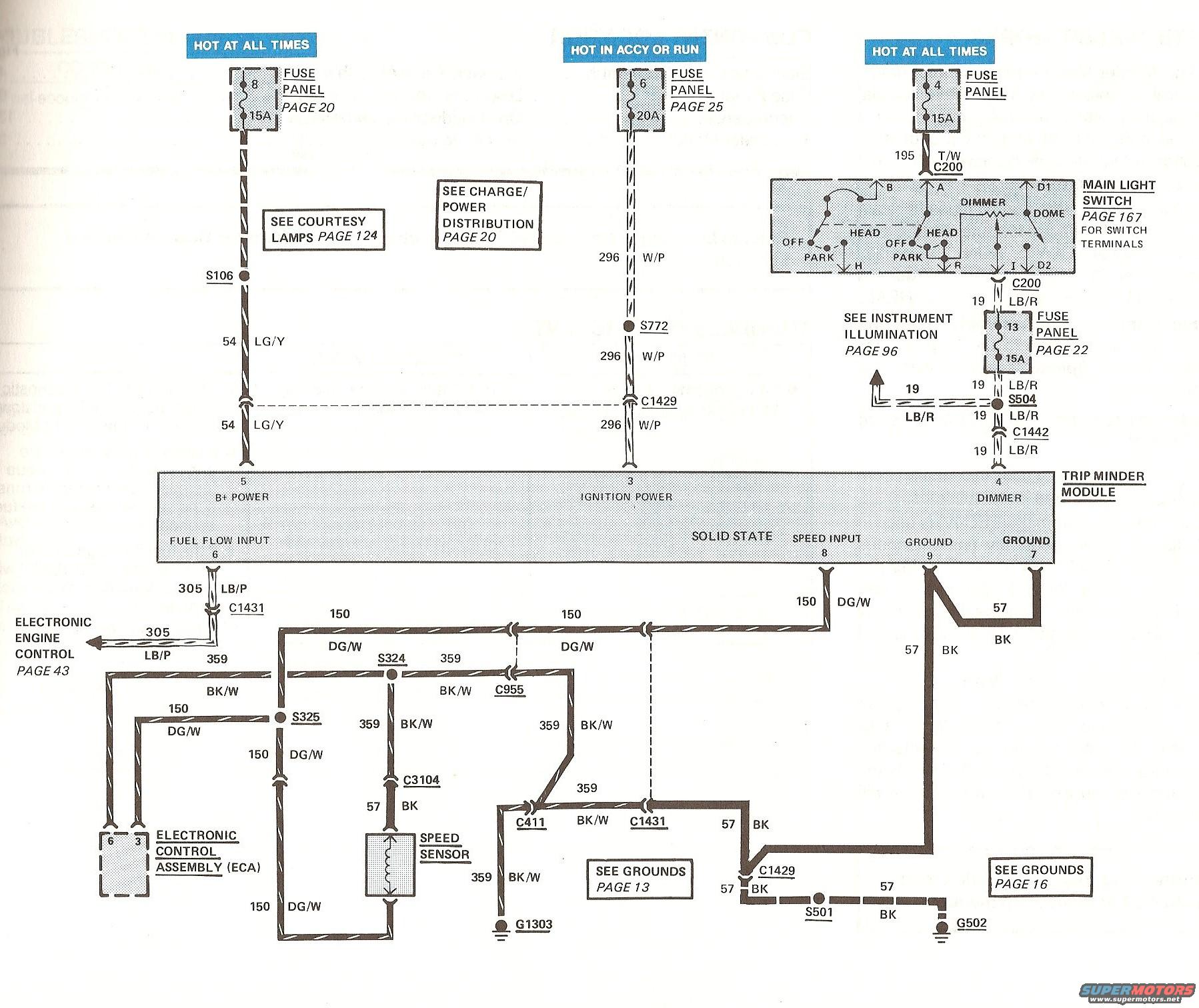
Ford Trip Minder Module Wiring Diagram - Power, Speed Sensor & Ground Circuits
Reference · 1983-1991 LTD Crown VictoriaAll 23 wiring diagrams
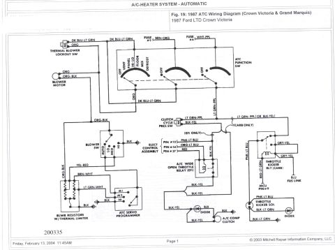
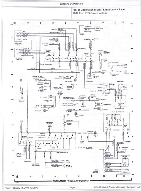
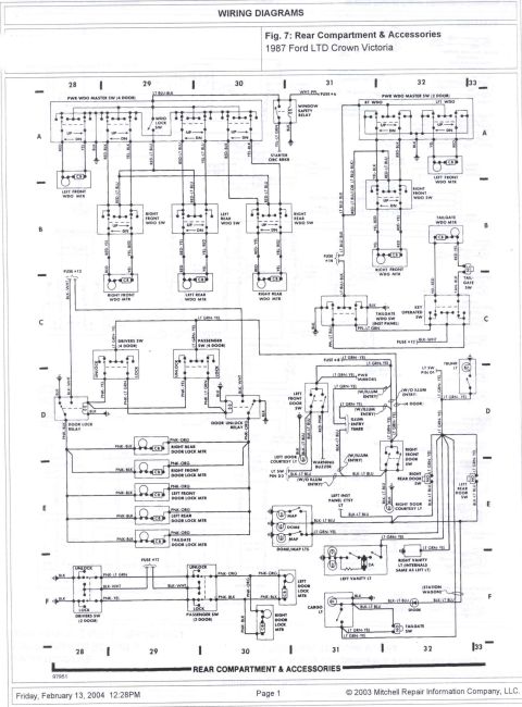
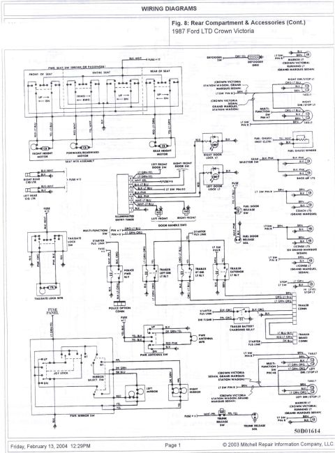
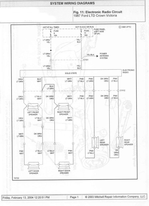
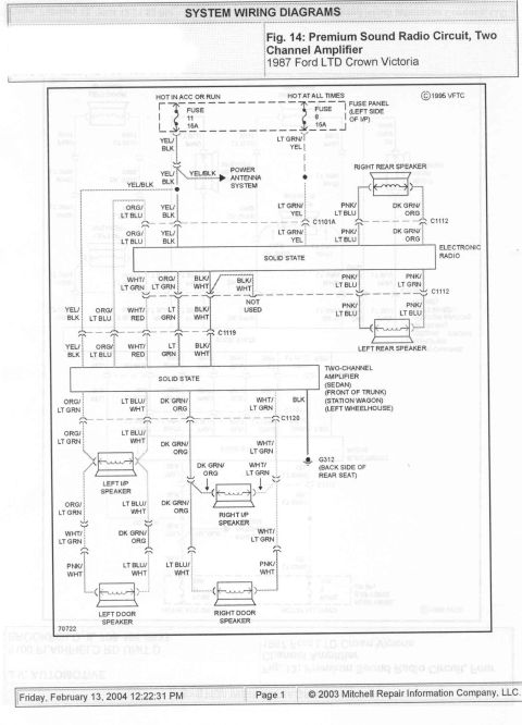
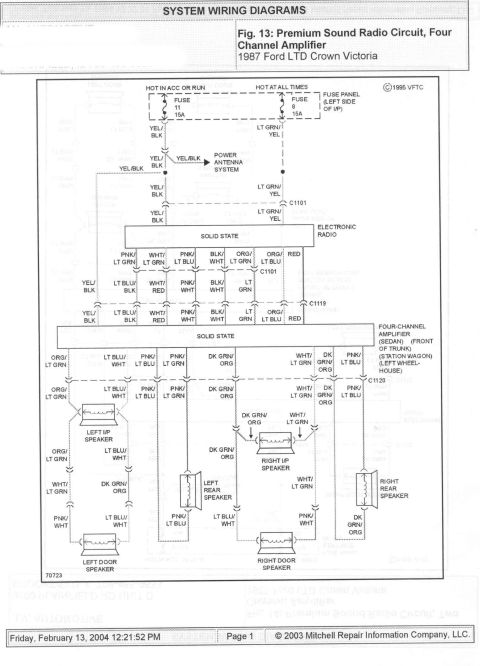
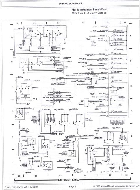
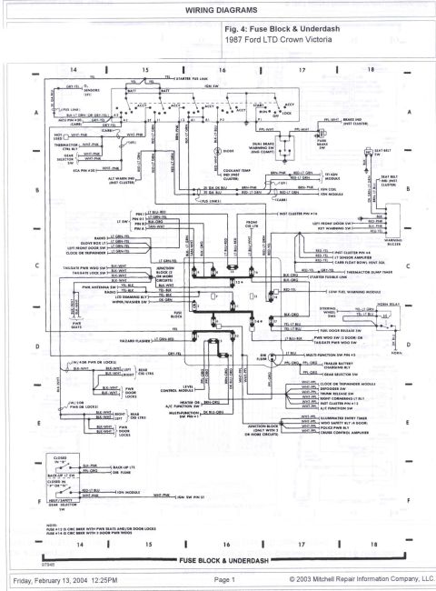
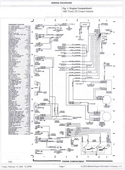
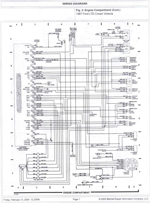

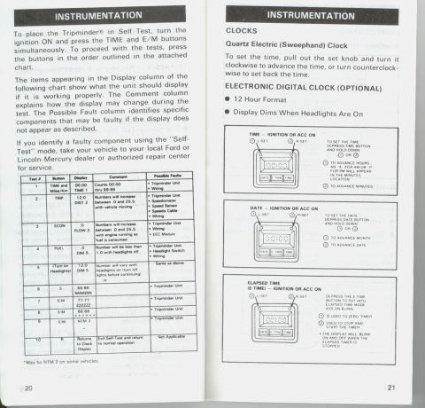
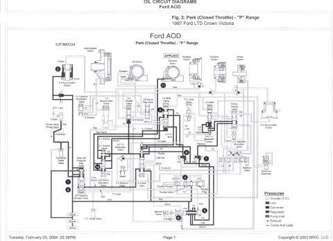
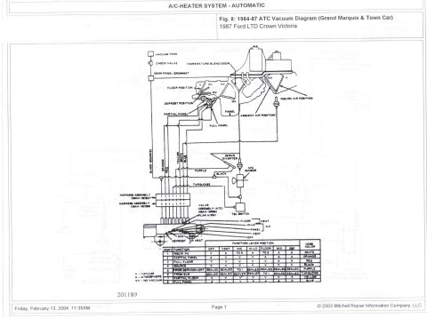
Wiring diagram for the Trip Minder module showing fuse panels, light switch, ECA and color-coded ground circuits.
Part of 1983-1991 Ford LTD Crown Victoria Wiring Diagrams
This document is a factory-style wiring diagram for the Ford Trip Minder module, a solid-state trip computer. It shows three power feeds: B+ power (pin 5) hot at all times through fuse 8 (15A), ignition power (pin 3) hot in ACCY or RUN through fuse 6 (20A) on circuit 296 W/P, and a dimmer feed (pin 4) hot at all times through fuse 4 (15A) via the main light switch (connector C200, circuit 195 T/W) and fuse 13 (15A) on circuit 19 LB/R. The fuel flow input (pin 6) runs on circuit 305 LB/P through connector C1431 to the Electronic Engine Control (page 43). The speed input (pin 8) uses circuit 150 DG/W, connected through splices S324/S325 and connectors C955, C3104, and C411 to the speed sensor and Electronic Control Assembly (ECA), with 359 BK/W wiring and ground G1303. Grounds at pins 7 and 9 use circuit 57 BK, routed through connector C1429 and splice S501 to ground G502. Cross-references include Courtesy Lamps (page 124), Charge/Power Distribution (page 20), Instrument Illumination (page 96), Main Light Switch terminals (page 167), and Grounds (pages 13 and 16). All wire circuit numbers, colors, splices, and connectors are labeled for diagnosis.
Is this accurate? Sign in to help verify it.
Frequently asked questions
- What fuses power the Ford Trip Minder module?
- Fuse 8 (15A, hot at all times) supplies B+ power to pin 5, fuse 6 (20A, hot in ACCY or RUN) supplies ignition power to pin 3 via circuit 296 W/P, and fuse 4 (15A, hot at all times) feeds the dimmer circuit through the main light switch and fuse 13 (15A) on circuit 19 LB/R to pin 4.
- What wire color is the Trip Minder speed input?
- The speed input at pin 8 uses circuit 150, dark green/white (DG/W), connected through splices S324 and S325 and connectors C955, C3104, and C411 to the speed sensor.
- Where does the Trip Minder get its fuel flow signal?
- The fuel flow input at pin 6 uses circuit 305 LB/P through connector C1431 to the Electronic Engine Control (see page 43).
- How is the Trip Minder module grounded?
- Grounds at pins 7 and 9 use circuit 57 black (BK), routing through connector C1429 and splice S501 to ground G502; the speed sensor circuit grounds at G1303 via 359 BK/W.
- Which connector links the dimmer circuit to the Trip Minder?
- Circuit 19 LB/R passes from the main light switch through connector C200, fuse 13 (15A), splice S504, and connector C1442 to the Trip Minder dimmer input at pin 4.


No comments yet.