Home/
Registry/
Ford/
LTD Crown Victoria/
1983-1991/
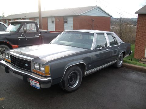
1985 Ford LTD Crown Victoria/
Photo
supermotors.net/registry/media/504702
1987 Ford LTD Crown Victoria Engine Compartment Wiring Diagram - Fig. 1

Mitchell wiring diagram Fig. 1 for the 1987 Ford LTD Crown Victoria engine compartment, with an alphabetical component locator (alternator, fuel pump relay, thermactor relays, trailer circuits) keyed to grid coordinates.
Part of 1983-1991 Ford LTD Crown Victoria Wiring Diagrams
This document is page 1 of a Mitchell Repair Information wiring diagram set, titled 'Fig. 1: Engine Compartment' for the 1987 Ford LTD Crown Victoria. It shows the engine compartment wiring schematic organized in a coordinate grid (columns 1-4, rows A-F) with a comprehensive Component Locator legend listing roughly 90 components and their grid coordinates, from the A/C compressor clutch (F 26, F 27) to the wiper/washer switch (A 24, B 24). The diagram itself covers exterior lighting circuits (cornering lights and relays, park lights, side markers, dual-beam and hi-beam headlights, with wire colors such as LT GRN-BLK, RED-BLK, BRN, WHT-LT BLU), the battery, starter relay and starter motor with a 20A in-line circuit breaker, ignition module, charging system (voltage regulator, alternator without IAR, and integral alternator regulator with terminal letters and wire colors/gauges like 16 GA BLK, 12 GA GRY, 14 GA DK GRN), horns and horn relay, and the wiper/washer system including the interval governor, wiper motor terminals (C, L, H) and run/park positions. Notes distinguish Crown Victoria vs Grand Marquis variants, EFI vs carbureted (ECA pins #1, #40 & 60), and with/without interval wipers and IAR. Printed footer dates the copy to February 13, 2004, © 2003 Mitchell Repair Information Company, LLC.
Is this accurate? Sign in to help verify it.
Frequently asked questions
- What vehicle does this wiring diagram cover?
- The document states it is Fig. 1: Engine Compartment for the 1987 Ford LTD Crown Victoria, with some callouts noting Grand Marquis-specific wiring differences.
- What wire colors go to the headlights?
- The dual beam headlights use LT GRN-BLK, RED-BLK, and BLK wires; the hi-beam headlights use two LT GRN-BLK wires and BLK. The left headlight LT GRN-BLK goes to pin #11 and RED-BLK to pin #10 of the multi-function switch.
- What size is the in-line circuit breaker in the starter/window safety circuit?
- The diagram shows a 20A in-line circuit breaker near the WDO safety relay (4 door) and starter relay.
- Where is the fuse block located on this diagram?
- The component locator lists the FUSE BLOCK at grid coordinates C-D 16.
- What wires connect to the voltage regulator?
- The voltage regulator shows YEL-WHT (A terminal), LT GRN-RED (I), ORG-LT BLU (F), and WHT-BLK (S), connecting to the alternator (without IAR) via WHT-BLK, ORG-LT BLU, and BLK-ORG wires.
Comments
More from this build








No comments yet.