Home/
Registry/
Ford/
Bronco/
1992-1996/
1993 Ford Bronco/
Photo
supermotors.net/registry/media/271187
Ford Bronco Gasoline Engine Vacuum Distribution Diagram - Hose Color Routing

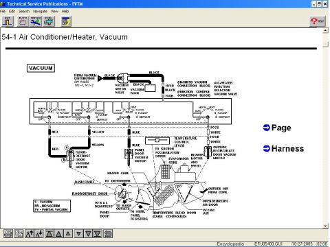
Reference · 1992-1996 BroncoAll 40 vacuum routing diagrams
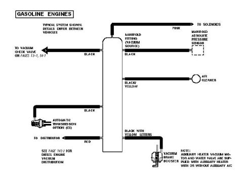

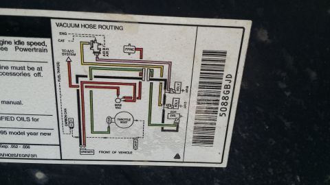
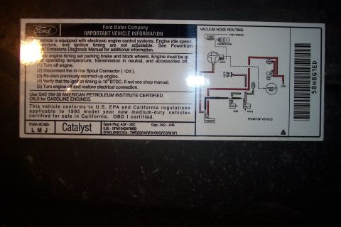
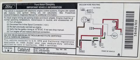
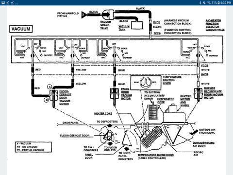
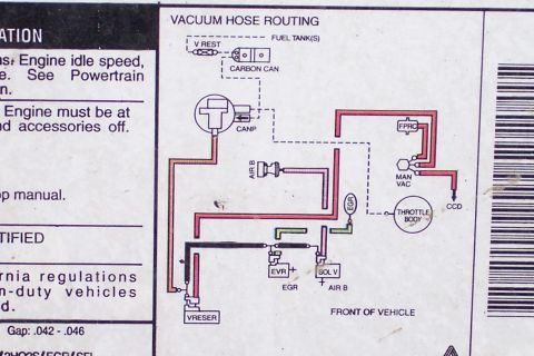
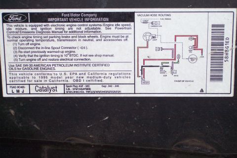
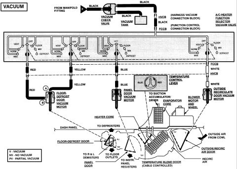






Vacuum routing diagram for gasoline engines showing manifold vacuum source, MAP sensor, check valve, distributor, and brake booster.
Part of 1992-1996 Ford Bronco Vacuum Routing Diagrams
This document is a vacuum distribution diagram for gasoline engines, showing a typical vacuum routing system from a central vacuum reservoir/tree connected to the manifold fitting (vacuum source). It notes that details differ between vehicles. Color-coded vacuum hoses branch from the central tree: a pink line runs to the solenoids, a black line runs to the vacuum check valve (referenced on pages 53-1 and 54-1) and another black line to the manifold fitting near the Manifold Absolute Pressure (MAP) sensor, a black/yellow line runs to the air cleaner, a black line serves the automatic transmission option (C6), a red line goes to the distributor, and a hose marked black with yellow letters supplies the vacuum brake booster. A note states that the auxiliary heater vacuum motor and water valve are supplied with the auxiliary heater with or without auxiliary A/C. A cross-reference directs readers to page 142-2 for diesel engine vacuum distribution. Readers can use this diagram to identify vacuum hose colors and trace which component each hose serves when diagnosing vacuum leaks or reconnecting lines after service.
Is this accurate? Sign in to help verify it.
Frequently asked questions
- What color is the vacuum hose that goes to the distributor?
- The hose to the distributor is red.
- Which vacuum line supplies the brake booster?
- The vacuum brake booster is supplied by a hose marked black with yellow letters.
- What color vacuum hose runs to the solenoids?
- A pink hose runs to the solenoids.
- Where is the vacuum source for this system?
- The vacuum source is the manifold fitting, located near the Manifold Absolute Pressure sensor.
- Does this diagram cover diesel engines?
- No, it shows gasoline engines; it refers to page 142-2 for diesel engine vacuum distribution.
- Are the auxiliary heater vacuum motor and water valve always included?
- Per the note, the auxiliary heater vacuum motor and water valve are supplied with the auxiliary heater, with or without auxiliary A/C.






No comments yet.