Home/
Registry/
Ford/
Bronco/
1992-1996/
1993 Ford Bronco/
Photo
supermotors.net/registry/media/275810
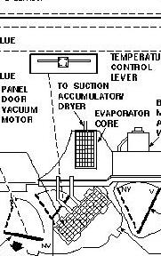
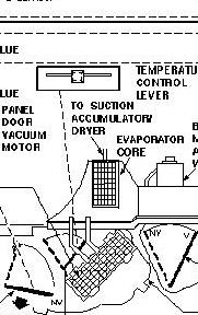
Ford Bronco HVAC Vacuum Diagram - Panel Door Vacuum Motor & Evaporator Core
Reference · 1992-1996 BroncoAll 40 vacuum routing diagrams
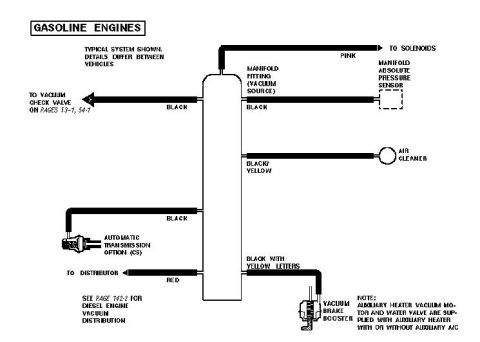
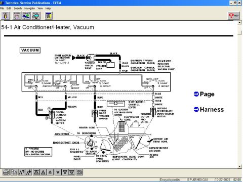

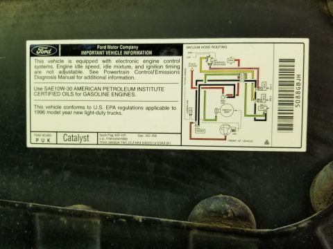
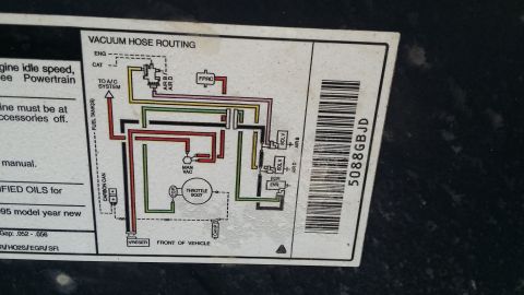
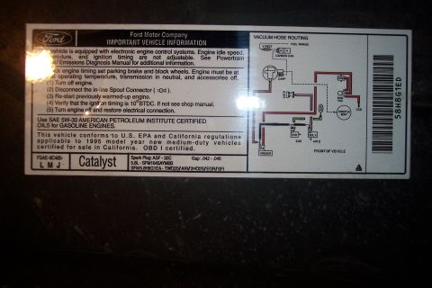
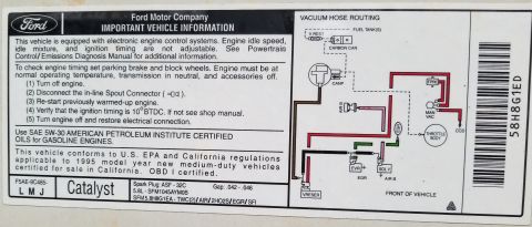

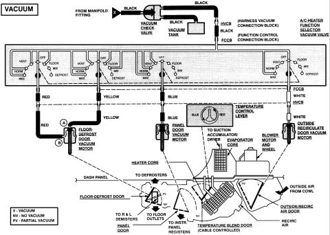




Air conditioning vacuum/airflow routing showing the panel door vacuum motor, temperature control lever, suction accumulator dryer and evaporator core layout.
Part of 1992-1996 Ford Bronco Vacuum Routing Diagrams
This document is a cropped scan of an HVAC (heating, ventilation, and air conditioning) vacuum routing / component diagram, uploaded as part of a set of Ford Bronco reference scans. The visible portion shows the climate control plenum area with several labeled components: the temperature control lever (with a slider-style control depicted at top), the panel door vacuum motor, the evaporator core (shown as a hatched rectangular element), a line labeled 'TO SUCTION ACCUMULATOR DRYER', and vacuum hoses identified by the color BLUE. A partially cut-off label at the right edge appears to identify another component (possibly the blower motor). The drawing shows hoses and tubes routing between the panel door vacuum motor, evaporator housing, and other HVAC hardware. Because the image is heavily cropped, no year, model, engine, part numbers, or legend/table data are visible, and several labels are truncated at the edges. A reader can learn the general placement of the panel door vacuum motor relative to the evaporator core and the routing of the blue vacuum line associated with the temperature/panel controls in the climate system.
Is this accurate? Sign in to help verify it.
Frequently asked questions
- What color vacuum hose goes to the panel door vacuum motor?
- The diagram labels the vacuum line associated with the panel door vacuum motor as BLUE.
- What HVAC components are identified in this diagram?
- The visible labels identify the temperature control lever, panel door vacuum motor, evaporator core, and a line running to the suction accumulator dryer.
- Where is the panel door vacuum motor shown in relation to the evaporator core?
- The panel door vacuum motor is shown on the HVAC plenum near the evaporator core, with the evaporator core drawn as a hatched rectangular element to its right in the diagram.
- Does this diagram show the suction accumulator dryer connection?
- It shows a callout labeled 'TO SUCTION ACCUMULATOR DRYER' pointing to a line/fitting near the evaporator core area, indicating where that connection routes.






No comments yet.