Home/
Registry/
Ford/
Bronco/
1992-1996/
1993 Ford Bronco/
Photo
supermotors.net/registry/media/601706
12V DC Motor Test Circuit Schematic with 15A Fuse & Multimeter (Multisim)
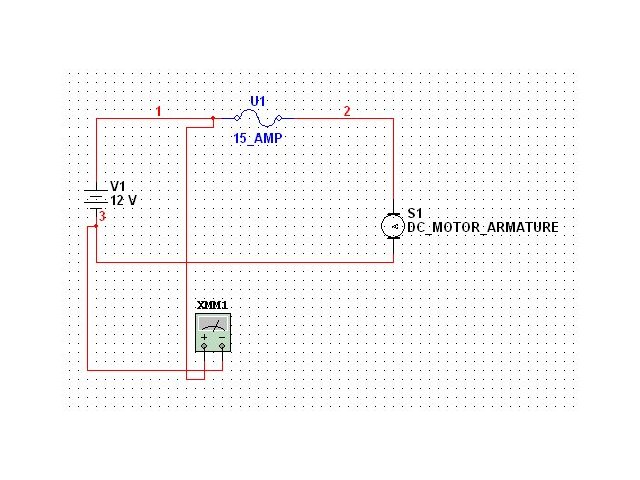
Reference · 1992-1996 BroncoAll 411 wiring diagrams
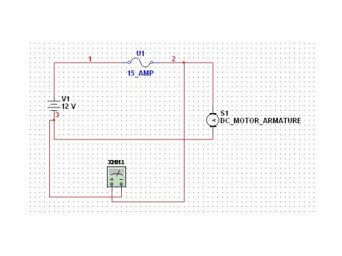
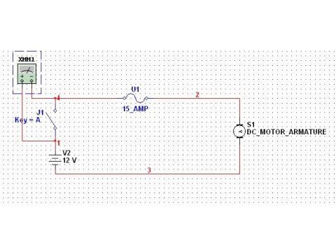
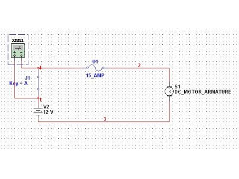
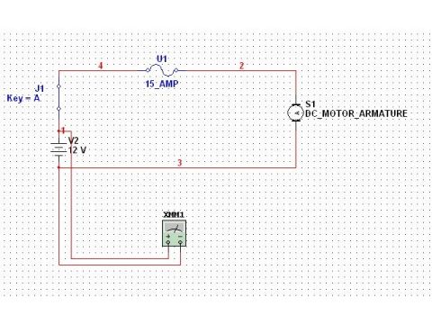
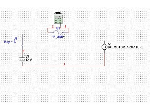
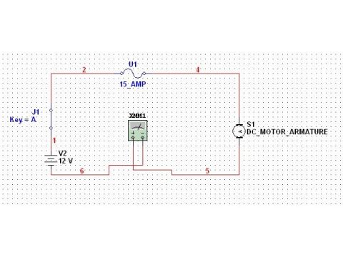







Electrical circuit schematic showing a 15 amp fuse, 12V source, DC motor armature, and multimeter.
Part of 1992-1996 Ford Bronco Wiring Diagrams
This document is a screenshot of a simple electrical circuit schematic created in circuit-simulation software (the style matches NI Multisim). It depicts a basic 12-volt automotive-style test circuit rather than a factory Ford wiring diagram. The circuit consists of a 12 V DC source labeled V1, a 15-amp fuse labeled U1 (15_AMP) in the positive supply line, a load labeled S1 identified as DC_MOTOR_ARMATURE, and a multimeter instrument labeled XMM1 connected into the circuit (apparently to take a measurement, consistent with the filename 'tstvlt1' suggesting a test-voltage exercise). Wire segments are numbered with net labels 1, 2, and 3. Current flows from the battery through the 15 A fuse to the motor armature and back, with the multimeter tied in near the battery/motor branch. A reader can learn the basic topology of a fused 12 V motor circuit and how a meter is connected for testing, but the document contains no vehicle-specific information: no wire colors, connector pin-outs, fuse box positions, part numbers, or year/model applicability. It appears to be part of a training or demonstration set alongside sibling files (AMP.jpg, FUSE.jpg, SRCVLT.jpg, switch open/closed diagrams) illustrating fundamental circuit measurements.
Is this accurate? Sign in to help verify it.
Frequently asked questions
- What voltage does the power source in this circuit provide?
- The source V1 is a 12 V battery/DC supply.
- What fuse rating is used in the circuit?
- U1 is labeled 15_AMP, i.e., a 15-amp fuse in the supply line.
- What is the load in this circuit?
- S1, labeled DC_MOTOR_ARMATURE, a DC motor armature.
- What measuring instrument is shown?
- XMM1, a multimeter symbol connected into the circuit for testing.
- Is this an actual Ford Bronco wiring diagram?
- No specific vehicle information appears; it is a generic simulated circuit with a 12 V source, 15 A fuse, DC motor armature, and multimeter.






No comments yet.