Nissan Micra Steering System Exploded Diagram & Torque Specs (ST-2)
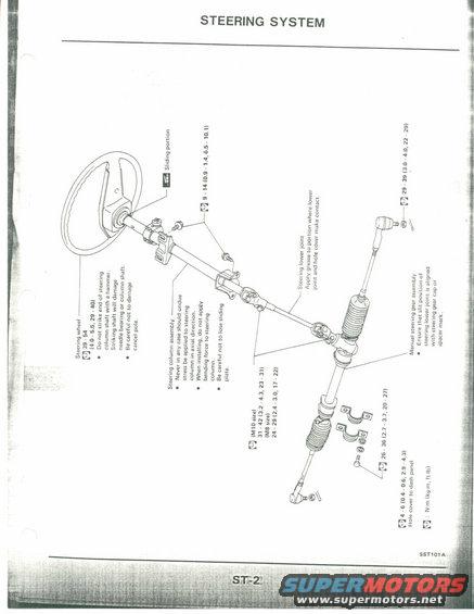
Exploded parts diagram of the steering system showing steering wheel, column assembly, gear, rack and tie rods with torque specifications.
This is page ST-2 of a factory service manual section titled "STEERING SYSTEM," showing an exploded parts diagram of a manual (non-power) rack-and-pinion steering system. The illustration depicts the steering wheel, steering column assembly, steering lower joint (universal joint), and the manual steering gear assembly with tie rod ends, boots, and mounting clamps. Torque specifications are given in N·m (kg-m, ft-lb): steering wheel nut 39-54 N·m (4.0-5.5 kg-m, 29-40 ft-lb); column fasteners 9-14 N·m; lower joint bolt 29-39 N·m; gear mounting bolts 31-42 N·m for M10 size and 24-29 N·m for M8 size; tie rod end nuts 26-36 N·m; and hole cover to dash panel screws 4-6 N·m. Cautionary notes warn against striking the steering column shaft with a hammer (which would damage the needle bearing or shaft), damaging the cancel pole, applying axial stress or bending force to the column, and losing the sliding plate. Grease application points are marked at the sliding portion and where the lower joint contacts the hole cover, and the reader is told to align the slit of the lower joint with the steering gear cap or spacer mark. Figure reference SST101A.
Is this accurate? Sign in to help verify it.
Frequently asked questions
- What is the steering wheel nut torque spec?
- 39 - 54 N·m (4.0 - 5.5 kg-m, 29 - 40 ft-lb).
- What torque should the steering gear mounting bolts be tightened to?
- M10 size: 31 - 42 N·m (3.2 - 4.3 kg-m, 23 - 31 ft-lb); M8 size: 24 - 29 N·m (2.4 - 3.0 kg-m, 17 - 22 ft-lb).
- What precautions apply when removing or installing the steering column?
- Do not strike the end of the steering column shaft with a hammer (it will damage the needle bearing or column shaft), be careful not to damage the cancel pole, never apply undue axial stress or bending force to the column, and be careful not to lose the sliding plate.
- Where should grease be applied on the steering lower joint?
- Apply grease to the portion where the lower joint and hole cover make contact; the sliding portion is also marked for grease.
- How should the steering lower joint be aligned with the steering gear?
- Ensure the slit position of the steering lower joint is aligned with the steering gear cap or spacer mark.
Comments
More from this build











No comments yet.