Nissan Micra Instrument Panel Exploded Diagram - Dash, Radio & Heater Finisher
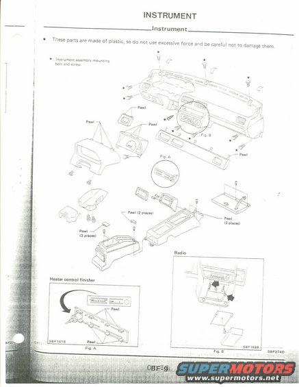
Exploded parts drawing of the instrument panel assembly with finishers, radio bezel, and heater control finisher.
This is a scanned page (BF-9) from a factory service manual's Body/Instrument section, showing an exploded parts diagram of the instrument panel (dashboard) assembly. A caution note advises that the parts are made of plastic, so excessive force should not be used and care taken not to damage them. Star symbols in the main exploded view identify the instrument assembly mounting bolts and screws. Numerous callouts labeled 'Pawl' (including 'Pawl (2 places)' and 'Pawl (3 places)') indicate the plastic retaining tabs on trim pieces such as the cluster lid, vents, finishers, and console pieces. Two inset detail figures are included: Fig. A shows the heater control finisher removal, with a curved arrow indicating how it is pried out and pawl locations marked (illustration reference SBF161B); Fig. B shows the radio removal from the center dash, with arrows indicating screw locations (illustration reference SBF162B). The page carries illustration code SBF274D. The page contains no fuse data, torque specifications, or part numbers; it serves as a disassembly/reassembly reference for locating fasteners and clips when removing dashboard trim, the heater control finisher, and the radio.
Is this accurate? Sign in to help verify it.
Frequently asked questions
- What precaution does the manual give for removing instrument panel parts?
- The parts are made of plastic, so do not use excessive force and be careful not to damage them.
- What do the star (★) symbols on the diagram indicate?
- They mark the instrument assembly mounting bolts and screws.
- What do Fig. A and Fig. B show?
- Fig. A shows the heater control finisher and its pawl locations (SBF161B); Fig. B shows the radio removal from the center dash (SBF162B).
- How are the trim pieces retained besides screws?
- By plastic pawls, with callouts noting 'Pawl (2 places)' and 'Pawl (3 places)' at various trim pieces.
Comments
More from this build











No comments yet.