1978 Ford Bronco Body & Chassis Mounts Diagram - Frame Mount Exploded Views

Reference · 1978-1979 BroncoAll 79 exploded parts diagrams
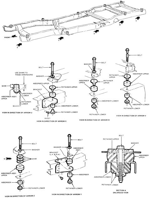
Exploded parts diagram of body-to-frame mount absorbers, retainers, washers and bolts shown from multiple arrow directions.
Part of 1978-1979 Ford Bronco Exploded Parts Diagrams
This document is an exploded parts diagram showing body and chassis mount locations and hardware for a Ford truck/Bronco-type frame. The top illustration depicts the complete frame from an overhead-front perspective, with arrows labeled U, V, W, X, Y, and Z marking the individual body mount positions along the frame rails, and 'FRONT' indicating orientation. Below, six detail views ('View in Direction of Arrow U/V/W/X/Y/Z') show the stack-up of components at each mount: bolt, washer, upper absorber (rubber body cushion), upper and lower retainers, lower absorber, shims, brackets, and (at the Arrow X mount) a rivet. The Arrow U view includes a shimming instruction: 'Use shims to these dimensions .83 / 1.27' (presumably inches/centimeters or a tolerance range). The Arrow Y view notes the bracket is used on both left- and right-hand sides. A 'Section A Enlarged View' cross-section shows how the bolt passes through the upper retainer, washer, upper absorber, lower absorber, and lower retainer when assembled. A reader can learn the correct order and orientation of body mount hardware at each frame position, which mounts require shims, and how the sandwiched rubber absorber assembly compresses between the body and frame.
Is this accurate? Sign in to help verify it.
Frequently asked questions
- How many body mount locations are shown on the frame?
- Six mount positions are identified on the frame, marked by arrows U, V, W, X, Y, and Z, each with its own exploded detail view.
- What parts make up a typical body mount in this diagram?
- A typical mount consists of a bolt, washer, upper retainer, upper absorber, lower absorber, and lower retainer; some positions also use shims, brackets, or a rivet.
- Which mounts use shims?
- The mounts shown in the direction of Arrow U and Arrow Z use shims. The Arrow U view instructs 'Use shims to these dimensions .83 / 1.27'.
- Which mount includes a rivet?
- The mount shown in the View in Direction of Arrow X includes a rivet securing the bracket.
- Is the bracket at the Arrow Y mount side-specific?
- The diagram labels it 'Bracket (L.H. & R.H.)', indicating brackets are used on both left- and right-hand sides.
No comments yet.