Ford F-100-F-350 & Bronco A/C Heater Register and Duct Assembly Diagrams

Reference · 1978-1979 BroncoAll 79 exploded parts diagrams


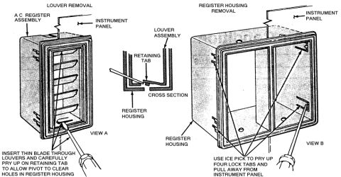




Assembly diagrams of right, left and center instrument panel HVAC duct and register assemblies with relay and wiring.
Part of 1978-1979 Ford Bronco Exploded Parts Diagrams
This document is a set of three exploded parts illustrations covering the heater/air conditioning register (vent) and duct assemblies for Ford F-100 through F-350 trucks and the Bronco. The top illustration shows the right register and duct, identifying the right register, the relay assembly (with a reference to View A), the duct assembly, the plenum chamber, and the portion of the instrument panel the register mounts into. An inset labeled View A details the relay assembly mounting, showing the relay assembly, wiring assembly (part reference 19A885), and mounting screw. The middle illustration shows the left register and duct, calling out the plenum chamber, duct assembly, part of the instrument panel, and left register. The bottom illustration shows the center register and duct, with callouts for the plenum chamber, duct assembly (including a flexible/bellows duct), part of the instrument panel, and center register. A reader can learn how the dash air registers connect to the plenum chamber via ducts, where the relay assembly and its wiring mount behind the right register, and the general orientation of these HVAC components behind the instrument panel. No torque values, fastener sizes, or model years are stated in the document itself.
Is this accurate? Sign in to help verify it.
Frequently asked questions
- What vehicles do these register and duct diagrams cover?
- The illustrations are labeled for Ford F-100 through F-350 trucks and the Bronco.
- Which registers (vents) are shown in this document?
- Three exploded views are shown: the right register and duct, the left register and duct, and the center register and duct.
- What does View A show?
- View A is an inset detailing the relay assembly behind the right register, showing the relay assembly, the wiring assembly (19A885), and its mounting screw.
- What connects the dash registers to the airflow system?
- Each register connects to the plenum chamber through a duct assembly that passes behind the instrument panel.
- Is any part number listed in the document?
- Yes, the wiring assembly in View A is identified as 19A885.






No comments yet.